Difference between revisions of "The 3D Preview"
| Line 58: | Line 58: | ||
<br> | <br> | ||
| + | |||
| + | Note that changing your view in the 3D preview window won't automatically update the current render camera. To update the current render camera to your current view, you must click the '''Copy this view to the current render camera''' button, which will be discussed in the '''3D Preview Bottom Toolbar''' section. | ||
== The 3D Preview Top Toolbar == | == The 3D Preview Top Toolbar == | ||
| Line 142: | Line 144: | ||
<br><br> | <br><br> | ||
| + | === Camera Control Buttons === | ||
| − | |||
| − | |||
| − | |||
| − | |||
| − | |||
It is important to be aware that changing the current view with either of these methods will not change the current camera position and orientation, as defined in the current Camera node in your scene. Instead it affects the 'Perspective view', one of a set of standard cameras provided by the '3D Preview' which are not linked to any camera node. These views are 'Perspective view', 'Top view', 'Bottom view', 'Front view', 'Back view', 'Left view' and 'Right view'. You can access each of these views by clicking the 'Select Camera' button second from the right on the toolbar at the bottom of the '3D Preview'. Clicking this button will open a list of available views, including 'Current render camera'. | It is important to be aware that changing the current view with either of these methods will not change the current camera position and orientation, as defined in the current Camera node in your scene. Instead it affects the 'Perspective view', one of a set of standard cameras provided by the '3D Preview' which are not linked to any camera node. These views are 'Perspective view', 'Top view', 'Bottom view', 'Front view', 'Back view', 'Left view' and 'Right view'. You can access each of these views by clicking the 'Select Camera' button second from the right on the toolbar at the bottom of the '3D Preview'. Clicking this button will open a list of available views, including 'Current render camera'. | ||
In order to set the render camera view to that which you have specified in the '3D Preview', you must use the 'Copy to current camera' button at the far left of the bottom toolbar in the '3D Preview'. This button will highlight whenever changes are made to the current view which are not reflected in the current camera. Pressing this button will sync the perspective camera with the current render camera. If you do not copy your current view to the render camera before you begin a render, your render will use the existing camera position and may not match your preview perspective. | In order to set the render camera view to that which you have specified in the '3D Preview', you must use the 'Copy to current camera' button at the far left of the bottom toolbar in the '3D Preview'. This button will highlight whenever changes are made to the current view which are not reflected in the current camera. Pressing this button will sync the perspective camera with the current render camera. If you do not copy your current view to the render camera before you begin a render, your render will use the existing camera position and may not match your preview perspective. | ||
Revision as of 05:59, 27 February 2019
Contents
About the 3D Preview[edit]
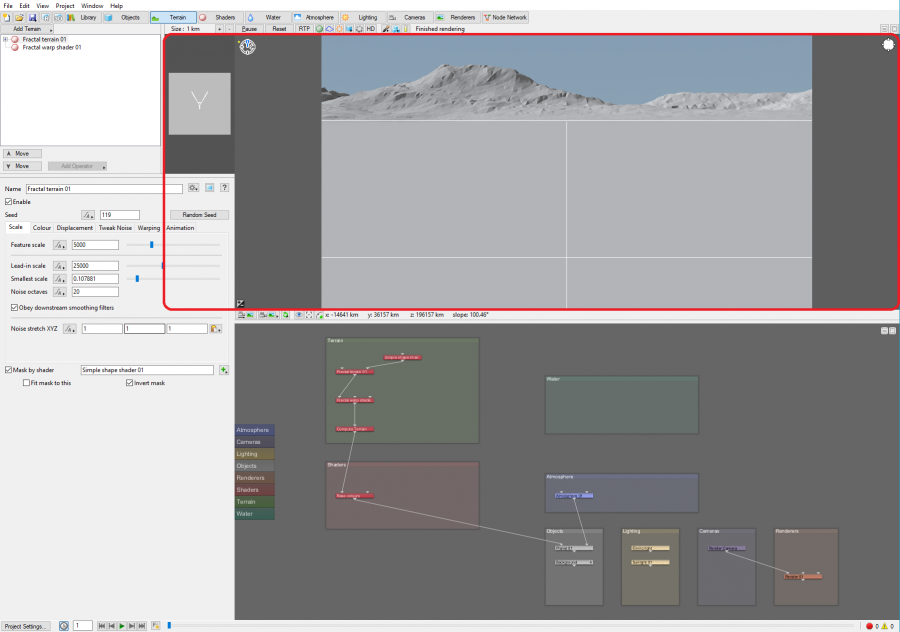
The 3D preview shows a preview of your current scene. It provides a simplified yet accurate view that renders quickly. The preview will update with every change you make to the settings of your scene, including any node settings.
[edit]
The 3D preview defaults to the perspective of the current render camera. You can freely change the camera perspective using either mouse and keyboard commands or the navigation tool.
[edit]
The controls for navigating with the mouse and keyboard are as follows:
- Alt+Left Click: Hold down these buttons and drag the mouse to rotate the camera.
- Alt+Middle Mouse Button: Hold down these buttons and drag the mouse to move the camera forward and back.
- Alt+Rick Click: Hold down these buttons and drag the mouse to move the camera left, right, up, or down.
[edit]
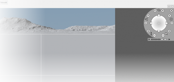
You can also adjust the camera with the navigation control tool located in the upper-right corner of the 3D Preview pane.
When you click this icon, the tool will expand to show a variety of control options.
Some of these controls may be familiar to you if you have experience with other 3D applications. The controls are as follows:
Note that changing your view in the 3D preview window won't automatically update the current render camera. To update the current render camera to your current view, you must click the Copy this view to the current render camera button, which will be discussed in the 3D Preview Bottom Toolbar section.
The 3D Preview Top Toolbar[edit]
The 3D preview top toolbar has a number of controls that allow you to change what you see in the 3D preview, as well as tools for interacting with your scene.
Turning Shaders, Atmosphere, and Lighting On and Off[edit]
The elements displayed in the 3D preview depend on the layout you're in. For example, in the Terrain layout, shaders, atmosphere, and lighting are disabled. This speeds up the preview and gives you a clear view of your landscape. You can control which elements are shown at any time with the 3 middle buttons on the top toolbar signified by a green sphere, a cloud shape, and a sun icon. These enable and disable Shaders, Atmosphere, and Lighting respectively. When enabled, these buttons will appear depressed and shaded.
Pause and Reset[edit]
To the left on the preview pane toolbar are the Pause and Reset buttons. Since the 3D preview is constantly updating to show you the results of every change, it is always taking CPU resources. If you have a lot of changes in mind and want to wait until you are finished with them, you may wish to pause the preview rendering until you are finished. Pause can also be useful when using the Painted shader and painting in the preview window. The Reset button simply resets the preview and begins rendering from scratch, which can be useful if you want to immediately trigger a refresh of the preview for any reason.
The Painted Shader and Measurement Tool[edit]
On the far right of the 3D preview top toolbar are the Painted Shader and Measurement Tool buttons. These are signified by a paintbrush and ruler, respectively.
The Measurement Tool[edit]
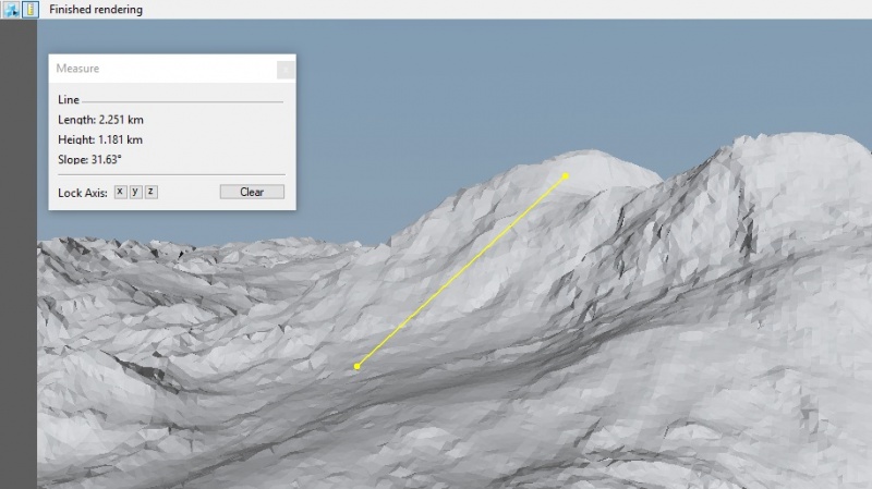
We'll cover the Measurement Tool first, because it is simpler. The Measurement Tool enables measurement mode, which allows you to measure the distance between two points in the 3D preview by clicking on them. In measurement mode, a measurement window will pop up with a display of the distance between the currently selected points, as well as some additional controls. Click in the 3D preview to define the first point of your measurement, then move to your destination point and click again. You will see a yellow line extend between the two points, and the distance will be displayed in the Measure window. The Measure window also allows you to restrict the measurement axis to x, y, or z, and clear the current measurement points (note that you may need to reset the preview window to remove the display of the current measurement). You can use the normal camera navigation controls in measurement mode, so if you wish to measure something outside of the current view, you can move the camera to accommodate that. To exit measurement mode, either close the pop-up Measure window, or click the Measurement Tool button again.
The Painted Shader Tool[edit]
The Painted Shader tool and the associated "Painted shader" node are among the most powerful systems in Terragen. The Painted shader allows you to control virtually any aspect of your scene by painting in the preview window. You can create terrain shapes, control texture distribution, and even create customized cloud shapes. The painting system relies on two elements: the paint strokes created with Painted Shader tool, and the "Painted shader" node.
Clicking the Painted Shader button brings up a menu of options. In its non-active state, the only option is Start painting shader, which has a sub-menu allowing you to either select an existing Painted shader to paint into, or create a new one and begin painting. Your existing Painted shaders will be listed at the top of this menu, above the "Create and paint new shader" option. To begin a painting session, select either an existing Painted shader, or create a new one with the menu option.
Once in a painting session, the Painted Shader button displays different options. You can switch between "Paint mode" and "Erase mode". Paint mode applies the current brush settings (specified in the Painted shader itself), and Erase mode uses the same brush settings, but applies an inverse effect to your paint strokes, removing existing painted areas. You can also use the "Stop painting shader" button to stop your painting session.
After paint mode is enabled, the settings window for the selected Painted shader will be opened, allowing you to adjust settings like "Brush size", "Brush falloff", "Flow", and "Colour". Please refer to the Node Reference for complete information on all Painted shader settings. In the 3D preview, a yellow dashed circle is displayed ,denoting the maximum area of your paint brush. The actual size of the painted stroke will be affected by the Falloff setting in the Painted shader. As you move the cursor around the preview window, you will also see terrain polygons highlighting under the cursor position. This denotes the rough center of the painted shader, and thus the center of the area at which the stroke would begin. To start painting, click the left mouse button and drag. You can make as many strokes as you want. Note, however, that "Undo" does not undo specific strokes. Rather, it Undo reverts the scene to a state prior to beginning your Painted Shader session. You can use the Eraser mode to remove strokes created in error. More on the use of the Painted shader is covered in the Node Reference and Shaders In-depth sections.
A helpful technique when using the Painted Shader tool is to allow the preview to fully compute to maximum detail, then press the Pause button and begin painting. This allows for maximum detail in viewing your painted strokes, and also prevents the preview from updating while you're painting which can make painting consistent strokes more difficult.
Rendering Status[edit]
The rightmost item on the 3D preview top toolbar is a display of the current status of the 3D preview rendering.
Since the preview is rendered progressively, it is helpful to know what detail level the preview is currently displaying. The detail level will be displayed numerically, beginning with "Rendering... detail 5", then doubling to 10, 20, 40, and finally 80. To save time and CPU resources, the preview has a set limit on the maximum detail, so once 80 is completed it will stop updating until another change is made. When rendering has completed, the update status will show "Finished rendering".
Mini Compass[edit]
In the upper-left corner of the 3D preview pane is a mini compass.
The top of the compass will always show the orientation of your current view; the compass will rotate as you move the camera.
Any lights in the scene are represented on the compass by small yellow circles.
Exposure Slider[edit]
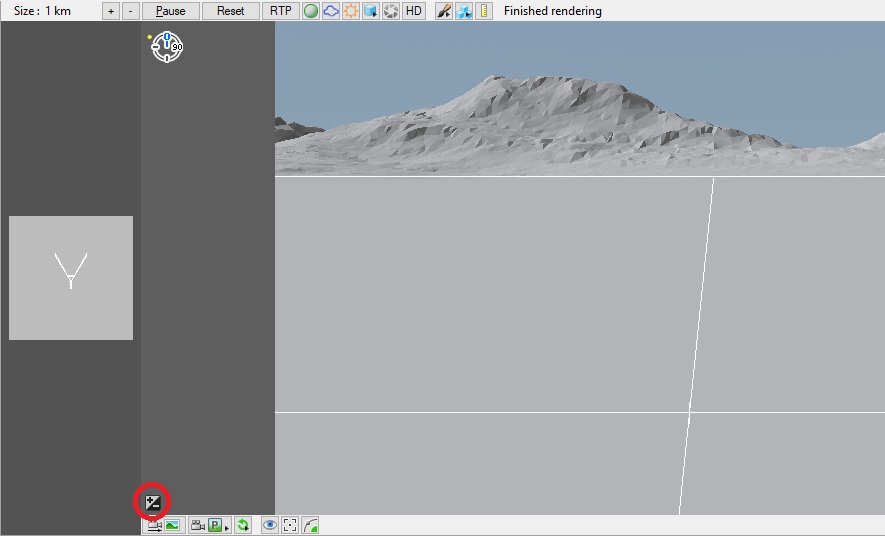
In the lower left of the 3D preview pane is the exposure slider.
When you press this button, it will open the exposure slider tool. This tool allows you to adjust the exposure value of the current camera, making it brighter or darker.
The 3D Preview Bottom Toolbar[edit]
The toolbar on the bottom of the 3D preview pane includes of a number of camera controls. It also displays the xyz coordinates of the mouse pointer if the mouse pointer is in the 3D preview pane.
Camera Control Buttons[edit]
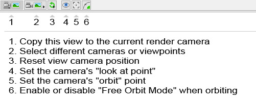
It is important to be aware that changing the current view with either of these methods will not change the current camera position and orientation, as defined in the current Camera node in your scene. Instead it affects the 'Perspective view', one of a set of standard cameras provided by the '3D Preview' which are not linked to any camera node. These views are 'Perspective view', 'Top view', 'Bottom view', 'Front view', 'Back view', 'Left view' and 'Right view'. You can access each of these views by clicking the 'Select Camera' button second from the right on the toolbar at the bottom of the '3D Preview'. Clicking this button will open a list of available views, including 'Current render camera'. In order to set the render camera view to that which you have specified in the '3D Preview', you must use the 'Copy to current camera' button at the far left of the bottom toolbar in the '3D Preview'. This button will highlight whenever changes are made to the current view which are not reflected in the current camera. Pressing this button will sync the perspective camera with the current render camera. If you do not copy your current view to the render camera before you begin a render, your render will use the existing camera position and may not match your preview perspective. At the bottom of the preview window is a set of 4 numbers labeled “x,” “y,” “z,” and “slope.” These will only appear when your mouse is positioned over the preview window. The x, y, and z figures indicate the current position of the scene element (usually the terrain) under the mouse cursor in the preview. Coordinates are measured in metric units, usually meters (‘m’) or kilometres (‘km’) and are relative to the coordinate origin. Slope indicates the slope of the terrain in that area and it is measured in degrees. Move the mouse around in the 3D preview and you will see the values update. These numbers can be extremely helpful in placing objects or fine-tuning surface mapping. The slope readout can be particularly useful in determining surface placement and distribution. In addition, you can easily copy these values into relevant settings in a particular node by right-clicking in the preview and selecting to copy the desired data (altitude, coordinates, or slope angle), then using the 'Paste button' next to an appropriate setting in a node. You can open this coordinate display in a separate floating window with the '3D Preview Location' option on the 'View' menu. In addition to the 'Copy to current render camera' and 'Select Camera' buttons, the bottom toolbar includes several other useful functions. Next to 'Select Camera' is the 'Reset Camera' button, which provides several options for resetting the view shown by the '3D Preview'. You can 'Reset to current render camera', 'Centre on focus point' (the focus point is set with the next button on the toolbar), 'Centre on object or shader', or 'Centre on origin' (the coordinate origin: 0,0). Remember that, like any change in the view shown in the preview window, you must press 'Copy to current render camera' to save your view in the current camera in order to use it in rendering. Next is the 'Look at point' button, which specifies the preview's “look at point,” a point in the scene toward which the camera will be oriented. Click the button then point and click on any part of the scene. You will see the polygon under your cursor highlight in yellow to indicate which polygon will be selected as the “look at point.” When you click, your camera will re-orient toward the selected point. This point is maintained throughout a session and you can use the command on the 'Reset Camera' button menu to recall your view to this point at any time. The last two buttons on the 'Bottom Toolbar' are both related to the camera “orbit” mode. The first allows you to select the “orbit point” in much the same way as the “look at point” function described above. The orbit point defines the point which the camera will reference when orbiting. The next and final button simply activates “Free Orbit Mode,” which allows the camera to roll freely during orbit movements, rather than being fixed to the original roll orientation. This is particularly useful when navigating with the camera at points far from the coordinate origin, for example on the other side of a planet, where the original roll value will not be parallel to the planet's surface. For further information on all functions and settings for the '3D Preview' please see the User Interface Reference.
In a graphical user interface (GUI) on a computer a toolbar is a row, column, or block of onscreen buttons or icons that, when clicked, activate certain functions of the program.
A shader is a program or set of instructions used in 3D computer graphics to determine the final surface properties of an object or image. This can include arbitrarily complex descriptions of light absorption and diffusion, texture mapping, reflection and refraction, shadowing, surface displacement and post-processing effects. In Terragen 2 shaders are used to construct and modify almost every element of a scene.
A single object or device in the node network which generates or modifies data and may accept input data or create output data or both, depending on its function. Nodes usually have their own settings which control the data they create or how they modify data passing through them. Nodes are connected together in a network to perform work in a network-based user interface. In Terragen 2 nodes are connected together to describe a scene.
