Difference between revisions of "Creating 360 Degree Renders with the Spherical Camera"
m (Getting link to .mp4 to work) |
m (Getting link to .mp4 to work) |
||
| Line 181: | Line 181: | ||
Click on the link below to see an example of an animated 360 degree environment.<br /> | Click on the link below to see an example of an animated 360 degree environment.<br /> | ||
| − | [[: | + | [[:Media:Tut_SphCam_37_SphericalRender.mp4]] |
<br /> | <br /> | ||
Latest revision as of 22:51, 18 February 2021

Click here to see an animated 360 degree environment sequence.
Contents
Overview[edit]
High Dynamic Range Imaging, or HDRI, is now a common place in the world of photography and visual effects, and there exists a great many cameras and tools to capture photographs of an environment, location or movie set that can later be used to augment and impart lighting, color, reflections and exposure data into a CGI workflow.
But what if your environment, location or world is CGI to begin with? What if it was created in Terragen in the first place; how might you use that environment’s lighting information in another 2D or 3D software package? The answer is to create the equivalent of an HDRI image of the environment within Terrgen, and to do this we’ll make use of Terragen’s spherical camera feature.
Terragen’s spherical camera allows you to render a 360 degree view of your environment. The rendered image can then be projected in your 2D or 3D software package to provide the lighting information to your application.
Spherical Environment - Still Image[edit]
The first thing we want to determine is whether to render a single image or an image sequence of the Terragen environment.
If your project’s final output is one rendered frame or perhaps you’re creating a game environment and constrained by the real time game engine to one or two images for a location’s time of day or night, then you probably don’t need an image sequence.
Let’s create a simple environment in which to place our spherical camera so we can render a 360 degree view of the environment. Starting with the default Terragen scene we’ll add a forest to our left and a rocky desert to our right.
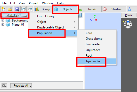
Click on the “Objects” button beneath the Main Menu, then the “Add Object” button and select “Population” then “TGO Reader” and choose a 3D tree object. none|531px|Add a population of 3D objects to the project.
From the tree Population's Distribution tab, click on the green “Plus” button next to the “Use Density shader” field and select “Create new shader” then “Colour shader” then “Simple Shape shader”.

Double click on the “Simple shape shader” in the Node Network pane to open its dialog window. By default the Simple Shape shader is positioned at the origin of our scene, and is 1000 square metres in size. Since we want it located to the left of the camera we can reposition it by typing a value of “-500” into the “Position” X axis.

If we go to a perspective view of our scene and press the Population’s “Populate Now” button we can see how the 3D tree object has been instanced to the left of the camera. Add a little variation to the forest by adjusting the “Minimum scale” and “Maximum scale” on the Population’s Scale tab.

Repeat this same procedure to the right of the camera, but this time choose Terragen’s built-in Rock object to populate with, and reposition the new Simple Shape shader’s X Position value to “500”.

You should end up with something like this.

By default our camera position is 10 meters or about 30 feet off the ground. Let’s lower the camera so it’s about the height of a person and zero out any rotation values.

Let the 3D Preview pane refresh fully and then click the “Ray Traced Preview” button above it, so that we can see the way in which the shadows fall across the terrain.

To adjust the direction of the shadows, click on the “Lighting” button and change the sun’s “Heading” and “Elevation” values as desired.

Finally change the Camera type’s radio button to Spherical. The 3D Preview pane will update to reflect the new type of camera.

Click on the “Renderers” button and select the Render node from the list. The width of the image should be twice as large as the height, so change the image width and height so that the final aspect ratio reads “2” and then click on the “Lock aspect ratio” button.
In order to preserve the high dynamic range lighting information of the rendered image, we need to save the image in the EXR format. On the Sequence/Output tab set your “Output image filename” path then set the frame range using the “Sequence first” and “Sequence last” fields, and finally click on the “Render Sequence” button or press “Ctrl-R” on your keyboard to render the frame..

After the image has been rendered and saved, you can load it into the 2D or 3D software package of your choice and use it to light your scene. All three example images below were rendered in a third party 3D software package using the lighting information that came from one Terragen rendered image.


Spherical Environment - Image Sequence[edit]
We need to create an image sequence when there is a “play of light” or interaction between the environment and the subject matter of a shot. For example, an aircraft flying through a break in the cloud cover might greatly benefit from an image sequence in which the lighting and reflections changed from a blue sky to grey clouds and back again.
In this scenario, it’s even possible to start with an animated motion path created in a different 3D software package. We can take advantage of Terragen’s “Import fbx scene” feature, found under the Main menu, to bring in the motion data and then apply it to the camera or object of our choice using Terragen’s Animation graph.

For this tutorial we only need the null objects and animation in metres, so uncheck the “Import cameras” and “Import lights” on the FBX Import: Scene dialog, then click on the “Choose File” button.

When the “Fbx Import: Animation” dialog appears, be sure that the “Base Stack” is highlighted and click “OK”.

In the Objects list there are five new null objects that came in from the FBX file. They contain position and rotation information that we can apply to other objects in the scene.

We need to create a new Terragen camera and then copy and paste the motions from the “null_SphericalCameraPath” to it. Click on the “Cameras” button at the top of the screen and then click on the “Add Camera” button. Rename the camera to “Camera Spherical” and change the camera type radio button to “Spherical”.

Press “F7” on your keyboard to bring up the Animation pane, or you can select it from the Main Menu > View > Animation Panel”.

The spherical camera does not show up in the Animation pane yet, because there are no keyframes assigned to it. Make sure you’re on frame 1 and then make a keyframe for its Position by clicking on the “Set animation key” and “Key All”.

The spherical camera will now be listed in the animation pane and the values in the Position field will turn green to indicate they have been keyframed.

Click the Animation pane “Maximize or restore the animation view” button to make it larger.

In the Animation pane click on the “Plus” button next to the spherical camera’s name and then on the “Plus” button next to its Position group to expand the XYZ channels. Do the same for the null_SphericalCameraPath object.

Before you copy and paste the keyframes from one item to another, make sure that the “Set the Current Frame” is positioned at the first frame that you want to have the motion data start at, for example Frame 0.

Select the null_SphericalCameraPath’s X channel and click on the “Fit to Curve” button at the bottom of the Animation pane.

Click on an empty area of the Animation graph and the press “Ctrl+A” to select all the keyframes, they will turn orange. Right-click and select “Copy” from the context menu or press “Ctrl+C” to copy the frames to the clipboard.

Then select the spherical camera’s Position X channel, click in an empty area of the Animation graph and press “Ctrl+A” to select all the keyframes, then right-click and select “Paste” from the context menu or press “Ctrl+V” to paste the frames into the X channel. Repeat this procedure for the Y and Z Position channels as well. If your camera has rotational data, repeat this procedure for the rotation channels as well.

In order to see the newly applied animation data on the spherical camera, we have to assign the camera to a renderer. Click on the “Renderers” button at the top of the screen, and then the “Add Renderer” button. Select the new Renderer, rename it to something descriptive if you wish and assign the spherical camera to it by clicking on the green “Plus” button next to the Camera field. Just as before, set the width and height to a 2:1 ratio.

Under the 3D Preview click on the “Select different cameras or viewports” button and choose the spherical camera. Scrub the timeline to refresh the 3D Preview and you will see the motion applied to the camera. Enable the RTP button to see the actual point of view from the camera.

Now that we have a camera flying above the terrain we can add a layer of clouds. Click the “Atmosphere” button, then the “Add Cloud Layer” button and choose the “Mid-level: AltoStratocumulus,Large” Easy Cloud preset.

Since our camera is around 3000 metres or 10,000 feet high, let’s lower the “Cloud base altitude” to around that height.

Render Considerations - GI Prepass[edit]
When rendering an image sequence we must first render and save the Global Illumination prepass. This is also referred to as the GI cache files, and they ensure that the lighting will not “flicker” from frame to frame in the final rendered image sequence.
Return to the Renderers Node list and click on the “GI Settings” button at the bottom of the Quality tab to open the GI Settings window. By default the GI Cache file is set to “No GI cache file”, so click on the radio button next to “Write to GI cache file” and navigate to a location to save the GI cache frames.

You do not have to render every frame of the animation when creating the GI cache files, just enough frames that Terragen can interpolate the GI lighting between frames. For example, if your camera and objects don’t move in your project you may only need to render one GI cache file. However, if your camera rotates 180 degrees in the shot you’ll need to render enough frames to provide coverage of the lighting in your project.
The spherical camera in this project is traveling in a straight line and is not passing through a lot of clouds, which could change the lighting, so we can render every fifth or even tenth frame for our GI cache file. To do this, set the “Sequence step” value on the Sequence/Output tab to “5” or “10”.
Clicking on the “Render Sequence” button will begin the render process for the GI prepass. When the “Write to GI cache file” is enabled, the Renderer will ignore the “Output image filename” and “Extra output images” settings on the Sequence/Output tab and only render the GI cache frames.
Once the GI cache frames are complete, change the radio button setting to “Read GI cache files” and select the cache frames. Set the “Blend mode” to “Interpolate for animation” and the “Number of files to blend” to “5”. This instructs Terragen to blend the 5 GI cache files nearest to the current frame being rendered. For example, if you rendered every 5 frames for your GI cache files starting at frame one, then when frame 17 of your final image sequence is being rendered Terragen will interpolate the GI cache files for frames 6,11,16,21, and 26 to determine the GI lighting for frame 17.
Render Considerations - Other Settings[edit]
On the Quality tab enable the “Motion blur” checkbox and set the motion blur type to “3D motion blur”. Enable the “Defer atmo/cloud” and “Defer all shading”, which will cause the atmosphere and terrain to render in the same pass. The Anti-aliasing value will greatly influence the render quality when the “Defer” passes have been enabled. Higher values will result in higher quality but also take longer to render.

On the Renderer’s Advanced tab, set the “Ray detail region” to “360 Degree detail (highest)”, this will ensure that Terragen takes into account all the shadows or reflections behind the camera’s position. Note, choosing this option also increases render times.

On the Sequence/Output tab, we need to save the image sequence in EXR format just as we did with the render of the still image in the previous example. After setting the file output path and file format, click on the “Check Animation...” button near the bottom of the pane. This feature quickly checks a number of the Renderer’s subdivision parameters and offers to automatically optimize those settings for rendering an image sequence. For this tutorial, click “Yes” to automatically optimize the settings.

Finally, set the “Sequence first” and “Sequence last” settings and reset the “Sequence step” value to 1 and click the “Render Sequence” button.

Click on the link below to see an example of an animated 360 degree environment.
Media:Tut_SphCam_37_SphericalRender.mp4
A shader is a program or set of instructions used in 3D computer graphics to determine the final surface properties of an object or image. This can include arbitrarily complex descriptions of light absorption and diffusion, texture mapping, reflection and refraction, shadowing, surface displacement and post-processing effects. In Terragen 2 shaders are used to construct and modify almost every element of a scene.