Vector Displacement Shader
Overview[edit]
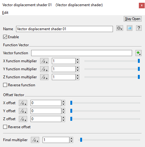
The Vector displacement shader can be used to displace a surface in any direction using a vector. The vector can be taken from a function input, a constant vector offset or a combination of both.
This node is especially useful when you want to apply displacement to a surface using a function network. Normally if a function network was connected to a shader input used for displacement you would not see any effect because the function nodes are not able to directly modify displacement like a shader can. The Vector displacement shader is able to bridge that gap and can take the output of a function network and convert it to displacement.
Using this node opens up the ability to use multiple 3D applications when sculpting terrain features. For example, you could create a procedural terrain in Terragen and export it as vector displacement data via an EXR image, then import the image into ZBrush for further refinement and sculpting, Save the Zbrush refinements as vector displacement data via an EXR image and import that back into Terragen via the Vector displacement shader.
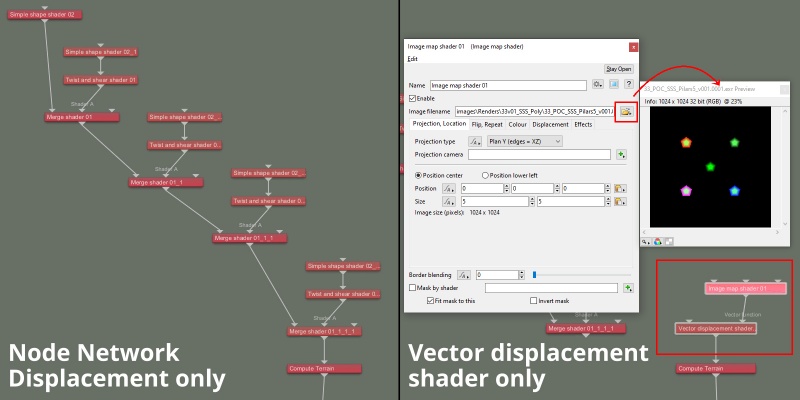
In the example image below, the image on the left relies on displacement of the planet surface by simple shape shaders and Twist and shear shaders, while the image on the right is based on a single rendered image of all the displacement shaders, then assigned to the Vector displacement shader’s Vector function. As you can see, there is no difference between the final renders, yet on a complex terrain the render times from the Vector displacement shader can be significantly less, as the displacements have been “baked in” to the rendered image.
Settings:
- Name: This setting allows you to apply a descriptive name to the node, which can be helpful when using multiple Vector displacement shader nodes in a project.
- Enable: When checked, the node is active and the settings below will affect the surface. When unchecked, the node is ignored.
Function Vector Section[edit]
The Function Vector parameters apply to the vector obtained from the Vector function input.
- Vector function: The function assigned to this setting is converted to displacement. The input expects a vector but will convert other input types according to the type conversion rules described here.
- X function multiplier: This value is multiplied with the X value obtained from the Vector function input. A value of 1, results in no change to the X vector value. Smaller values would reduce the X vector value, for example a value of 0.5 would result in a displacement amount that’s half of the Vector function’s input. Negative values cause the vector’s sign to switch from positive to negative, or visa-versa, therefore a displacement that is pointed outwards could be turned inwards.
- Y function multiplier: This value is multiplied with the Y value obtained from the Vector function input. A value of 1, results in no change to the Y vector value. Smaller values would reduce the Y vector value, for example a value of 0.5 would result in a displacement amount that’s half of the Vector function’s input. Negative values cause the vector’s sign to switch from positive to negative, or visa-versa, therefore a displacement that is pointed upwards could be turned downwards.
- Z function multiplier: This value is multiplied with the Z value obtained from the Vector function input. A value of 1, results in no change to the Z vector value. Smaller values would reduce the Z vector value, for example a value of 0.5 would result in a displacement amount that’s half of the Vector function’s input. Negative values cause the vector’s sign to switch from positive to negative, or visa-versa, therefore a displacement that is pointed outwards could be turned inwards.
- Reverse function: When checked, the value obtained from the Vector function input is reversed. In other words each component of the vector has its sign changed. This happens after the vector value has been multiplied by the function multiplier values above.
Offset Vector Section[edit]
The parameters under this section do not require that a shader or function nodes be assigned to the Vector Function setting. Values applied to the Offset Vector settings apply a constant offset to any displacement by shifting the entire surface the Vector Displacement shader is applied to.
- X offset: This value can be used to shift displacement along the X axis.
- Y offset: This value can be used to shift displacement along the Y axis.
- Z offset: This value can be used to shift displacement along the Z axis.
- Reverse offset: When checked, the offset vector is reversed. In other words each component of the vector has its sign changed.
- Final multiplier: The calculated displacement vector (the vector function and/or the offset) is multiplied by this value as the last step before being added to the current surface displacement.
Tutorials and Resources[edit]
Vector displacement shader - Terragen to Zbrush and back! Coming shortly.
Literally, to change the position of something. In graphics terminology to displace a surface is to modify its geometric (3D) structure using reference data of some kind. For example, a grayscale image might be taken as input, with black areas indicating no displacement of the surface, and white indicating maximum displacement. In Terragen 2 displacement is used to create all terrain by taking heightfield or procedural data as input and using it to displace the normally flat sphere of the planet.
A shader is a program or set of instructions used in 3D computer graphics to determine the final surface properties of an object or image. This can include arbitrarily complex descriptions of light absorption and diffusion, texture mapping, reflection and refraction, shadowing, surface displacement and post-processing effects. In Terragen 2 shaders are used to construct and modify almost every element of a scene.
Literally, to change the position of something. In graphics terminology to displace a surface is to modify its geometric (3D) structure using reference data of some kind. For example, a grayscale image might be taken as input, with black areas indicating no displacement of the surface, and white indicating maximum displacement. In Terragen 2 displacement is used to create all terrain by taking heightfield or procedural data as input and using it to displace the normally flat sphere of the planet.
A vector is a set of three scalars, normally representing X, Y and Z coordinates. It also commonly represents rotation, where the values are pitch, heading and bank.
A single object or device in the node network which generates or modifies data and may accept input data or create output data or both, depending on its function. Nodes usually have their own settings which control the data they create or how they modify data passing through them. Nodes are connected together in a network to perform work in a network-based user interface. In Terragen 2 nodes are connected together to describe a scene.


