Multiply Scalar
Overview[edit]
The Multiply family of nodes allow you to multiply the colour/scalar/vector coming into the Main Input by the color/scalar/vector coming into Input 2.
The Multiply Scalar node multiplies two scalars together. It wants the incoming data to be scalars, and will convert colours and vectors to scalars if necessary as follows:
- Colour data is converted to scalar based on the component’s luminance values. The math for this is: 0.2125 * r + 0.7152 * g + 0.0724 * b.
- Vector data is converted to scalar data, based on the length of the vector from the zero origin. The math for this is: square_root(x * x + y * y + z * z).
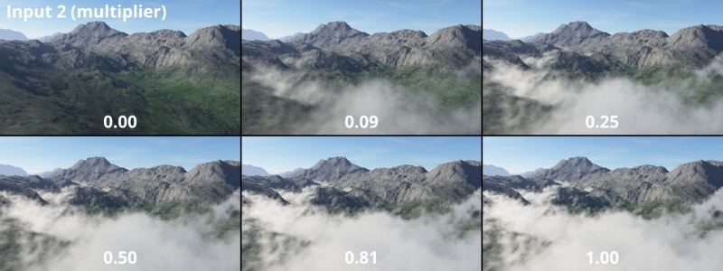
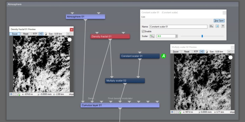
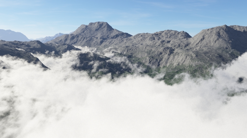
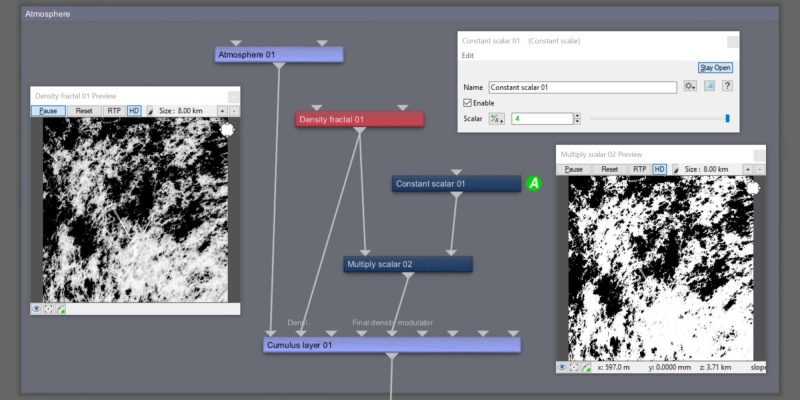
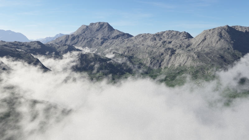
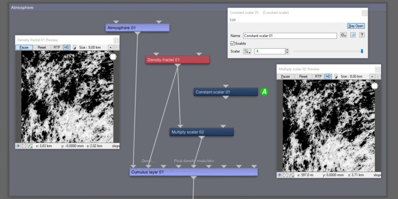
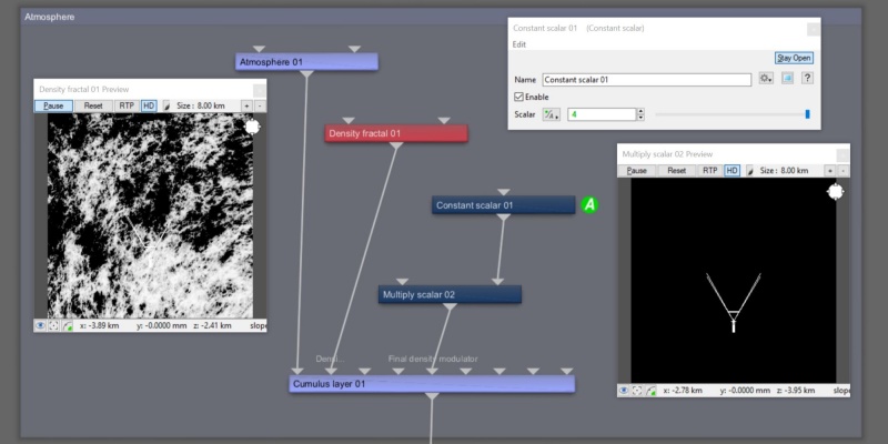
The following example illustrates the effect of the Multiply scalar node on a cloud layer’s Final density parameter as the value from Input 2 changes.
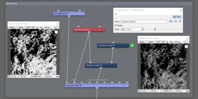
In this example, the value assigned to Input 2 is 0.5, which results in the cloud layer’s Final density value to be half as dense as the source values assigned to the Main Input.
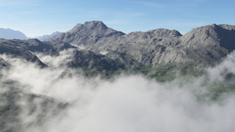
In this example, the value assigned to Input 2 is 4.0, which results in the cloud layer’s Final density value to be four times as dense as the source values assigned to the Main input.
If a shader or function nodes are not connected to Input 2, the Main Input is simply passed through the Multiple scalar node’s output.
If a shader or function nodes are not connected to the Main Input, a value of 0, or black, is passed through the node.
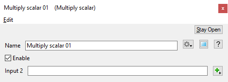
All nodes in this family have just one setting, which lets you assign a shader or function nodes to Input 2.
Settings:
- Name: This setting allows you to apply a descriptive name to the node, which can be helpful when using multiple Multiply Scalar nodes in a project.
- Enable: When checked, the node is active and the multiplication operation will take place. When unchecked the values assigned to its Main Input, if any, are passed through, otherwise a value of 0 is passed through.
- Input 2: The values from the shader or function nodes assigned to this setting are multiplied with the Main Input values. When nothing is assigned, the Main Input values, if any, are passed through. If the Main Input is unassigned, the output from the node is 0.
A scalar is a single number. 1, 200.45, -45, -0.2 are all examples of scalar values.
A vector is a set of three scalars, normally representing X, Y and Z coordinates. It also commonly represents rotation, where the values are pitch, heading and bank.
This is essentially the brightness of the colour. Terragen converts RGB colours to greyscale by taking the luminance of the colour.
A parameter is an individual setting in a node parameter view which controls some aspect of the node.
A shader is a program or set of instructions used in 3D computer graphics to determine the final surface properties of an object or image. This can include arbitrarily complex descriptions of light absorption and diffusion, texture mapping, reflection and refraction, shadowing, surface displacement and post-processing effects. In Terragen 2 shaders are used to construct and modify almost every element of a scene.
A single object or device in the node network which generates or modifies data and may accept input data or create output data or both, depending on its function. Nodes usually have their own settings which control the data they create or how they modify data passing through them. Nodes are connected together in a network to perform work in a network-based user interface. In Terragen 2 nodes are connected together to describe a scene.
