Difference between revisions of "Compositing Terragen Render Elements"
m (fixed typo) |
(Added description and example images for Sample Rate render element.) |
||
| (4 intermediate revisions by the same user not shown) | |||
| Line 61: | Line 61: | ||
[[File:CmpRndElm_07_tgAlpha.jpg|none|867px|tgAlpha = tgSurfAlpha + tgAtmoAlpha + tgCloudAlpha]] | [[File:CmpRndElm_07_tgAlpha.jpg|none|867px|tgAlpha = tgSurfAlpha + tgAtmoAlpha + tgCloudAlpha]] | ||
| + | |||
| + | A question often asked is “Why does the alpha channel image contain colour values?” and “How do I use it?” | ||
| + | |||
| + | |||
| + | In Terragen, the Rayleigh scattering feature takes into account that the atmosphere’s opacity can vary at different wavelengths, and this information can be recorded in the red, green and blue channels of a rendered image. This is called a “Chromatic” alpha channel, and by using the RGB channels instead of the familiar alpha channel, which only contains one value per pixel, you have more accurate control over any post production changes you might want to make, especially to the cloud layers and atmosphere. | ||
| + | |||
| + | |||
| + | To use the chromatic alpha channel, you first need to multiply an inverted version of it over the non-Terragen background render element. Then merge any Terragen RGB render elements on top using Additive mode. | ||
| + | <ul> | ||
| + | * Invert the chromatic alpha channel by adding a Channel Boolean node, with its Operation mode set to negative. | ||
| + | * Merge the inverted chromatic alpha channel with the non-Terragen render element, setting the Apply Mode to multiply. | ||
| + | * Merge the Terragen RGB render element, such as the tgRGB, in additive mode. In Fusion Studio, this means the Apply Mode = Normal, Operator = Over, and Alpha Gain = 0. | ||
| + | </ul> | ||
| + | |||
| + | |||
| + | [[File:CmpRndElm_06_ChromaticAlphaChannels_0001.jpg|none|867px|Compositing the Terragen rendered elements on top of a non-Terragen element using the chromatic alpha channels.]] | ||
| Line 97: | Line 113: | ||
[[File:CmpRndElm_15_tgCloudPos.jpg|none|867px|tgSurfPos combined with tgCloudPos]] | [[File:CmpRndElm_15_tgCloudPos.jpg|none|867px|tgSurfPos combined with tgCloudPos]] | ||
| + | |||
| + | |||
| + | ==Normals== | ||
| + | |||
| + | The “tgSurfNormal” render element contains data describing the 3D vector of a line perpendicular to the surface of an object or terrain, in world space. Each pixel channel contains values from -1.0 to +1.0. The X Normals are mapped to the Red channel, and values below 0.0 to -1.0 indicate the underlying geometry is pointing in the direction of the -X axis in world space, while values above 0.0 to +1.0 point towards the +X axis. The Y Normals are mapped to the Green channel, and values lower than 0.0 point downward while values above 0.0 point upwards. The Z Normals are mapped to the Blue channel and values below 0.0 point towards the -Z axis, while values above 0.0 point towards the +Z axis in world space. | ||
| + | |||
| + | Depending on the compositing software being used, it may be necessary to reverse the Z channel and/or swap Y and Z channels if you need to combine the render element with normal passes from other software. | ||
| + | |||
| + | [[File:CmpRndElm_16_tgSurfNormals.jpg|none|867px|tgSurfNormal]] | ||
| + | |||
| + | |||
| + | ==Surface Diffuse Colour== | ||
| + | |||
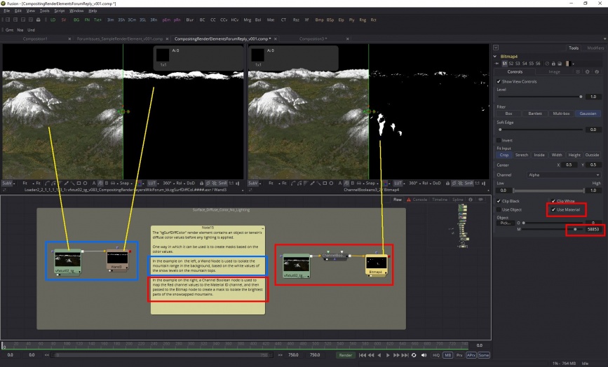
| + | The "tgSurfDiffColor" render element contains an object or terrain's diffuse color values before any lighting is applied. | ||
| + | |||
| + | One way in which it can be used is to create masks based on the color values. | ||
| + | |||
| + | [[File:CmpRndElm_17_tgSurfDiffCol.jpg|none|867px|tgSurfDiffCol]] | ||
| + | |||
| + | |||
| + | ==Sample Rate== | ||
| + | |||
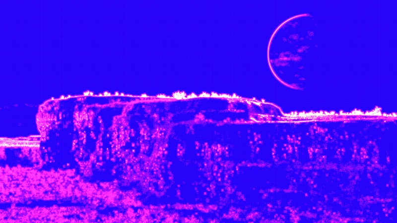
| + | The Sample Rate render element shows the distribution of “ray-traced subpixel samples” by the adaptive sampler. The colours represent a percentage of the maximum possible samples for a given anti-aliasing value. For example, 64 is the maximum possible samples for an anti-aliasing value of 8. | ||
| + | |||
| + | [[File:CmpRndElm_07_RenderPixelSampler_AA8_64Samples.png|none|470px|Pixel Sampler window showing anti-aliasing value set to 8, and the maximum number of possible samples, 64.]] | ||
| + | |||
| + | |||
| + | When viewing the image as an EXR, clamp the values at 1 (white) for ideal viewing. When clamped, the relationship of colour to the maximum possible samples is as follows: | ||
| + | |||
| + | * Fully white pixels = 100% | ||
| + | * Magenta pixels = 10% | ||
| + | * Blue pixels = 1% | ||
| + | * Black pixels = 0 samples. | ||
| + | |||
| + | Note, that although a pixel might contain no samples, interpolation occurs wherever samples are sparse. | ||
| + | |||
| + | When viewing as an unclamped EXR, the green channel goes from 0 to 1 to represent the fraction of samples, while the red and blue channels may exceed 1 as they are equal to the green channel multiplied by 10 and 100, respectively. | ||
| + | {| | ||
| + | |- | ||
| + | | [[File:CmpRndElm_08_SampleRate_Clamped.JPG|none|800px|Close up detail showing pixel values when clamped and unclamped.]] | ||
| + | |- | ||
| + | | [[File:CmpRndElm_09_SampleRateElement.JPG|none|800px|Sample Rate render element.]] | ||
| + | |} | ||
| + | |||
| + | <br /n> | ||
Latest revision as of 18:12, 24 February 2022
Contents
Rebuilding the Image from Lighting Elements[edit]
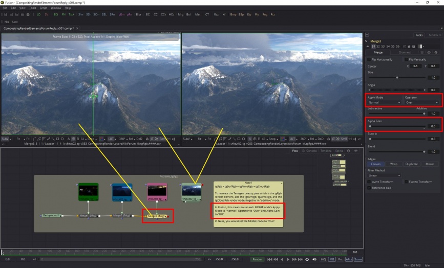
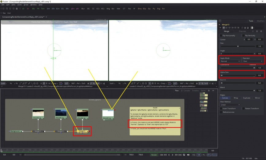
Compositing with Terragen's render elements allows you to recreate and fine-tune the final rendered image or "beauty pass". The compositing project should be set up in linear colour space and you will use an "Additive" workflow approach, which means setting the render element's merge or blending mode to the equivealent of "additive" in your 2d software package. In the Nuke software, this means setting the merge node to "Plus", while in the Fusion software, this means setting the merge node's "Apply Mode" to "Normal", "Operator" to "Over", and "Alpha Gain" to "0.0".
tgRgb[edit]
The simplest example of combining render elements to match the Terragen beauty pass, which is sufficient for many projects, is this:
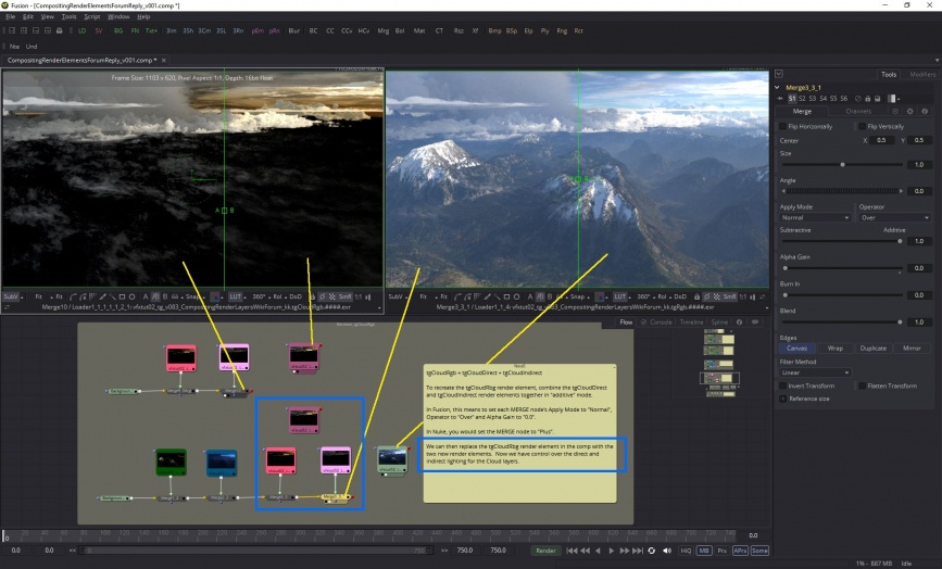
tgRgb = tgSurfRgb + tgAtmoRgb + tgCloudRgb
Note that each of these render elements are blended or merged together in an "additive" way, and that the end result matches the Terragen beauty pass.
tgSurfRgb[edit]
Sometimes you'll want to adjust or fine-tune your image, so each of the three "Rgb" render elements above can be recreated by combining other render elements. The newly combined elements then replace the "Rgb" render element in the comp.
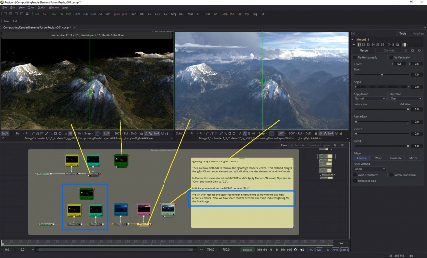
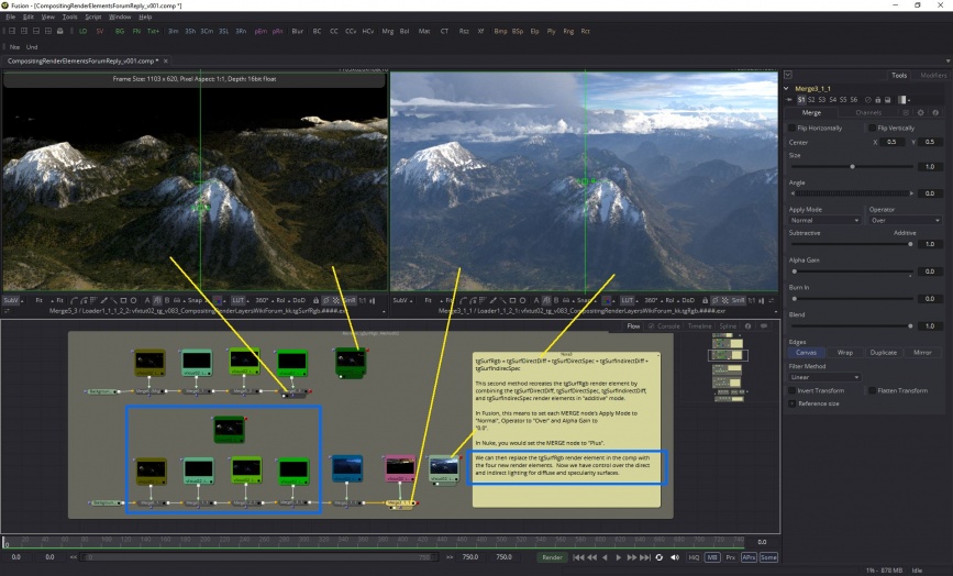
There are two methods for recreating the "tgSurfRgb" element. The first gives you control over direct and indirect lighting. The second gives you control over the diffuse and specular as well.
For control over direct and indirect lighting on a surface use:
tgSurfRgb = tgSurfDirect + tgSurfIndirect.
For control over the diffuse and specular lighting on a surface choose this:
tgSurfRgb = tgSurfDirectDiff + tgSurfDirectSpec + tgSurfIndirectDiff + tgSurfIndirectSpec.
As you can see, using either of these methods results in matching the Terragen beauty pass, and adds the ability to "dial in" the amount of surface lighting you want.
tgAtmoRgb[edit]
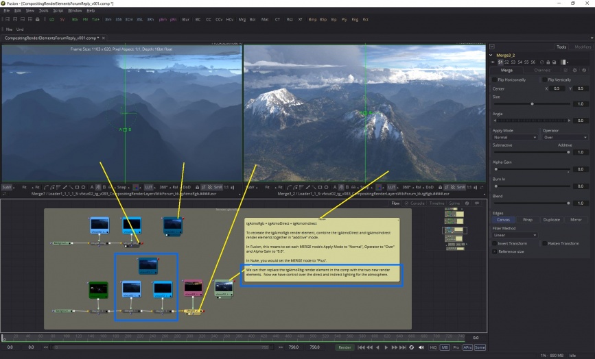
Likewise the atmosphere "tgAtmoRgb" render element can also be recreated by combining the tgAtmoDirect and tgAtmoIndirect render elements, which will give you control over the atmosphere's direct and indirect lighting.
tgAtmoRgb = tgAtmoDirect + tgAtmoIndirect
tgCloudRgb[edit]
And finally, the clouds "tgCloudRgb" render element can be recreated in a similar fashion, by combining the "tgCloudDirect" and "tgCloudIndirect" render elements.
tgCloudRgb = tgCloudDirect + tgCloudIndirect
Results of additive workflow[edit]
In the image below we can see the compositing node layout and the results of the “additive” workflow.
tgAlpha[edit]
The “tgAlpha” channel can also be reconstructed with alternate render layers: tgAlpha = tgSurfAlpha + tgAtmoAlpha + tgCloudAlpha
A question often asked is “Why does the alpha channel image contain colour values?” and “How do I use it?”
In Terragen, the Rayleigh scattering feature takes into account that the atmosphere’s opacity can vary at different wavelengths, and this information can be recorded in the red, green and blue channels of a rendered image. This is called a “Chromatic” alpha channel, and by using the RGB channels instead of the familiar alpha channel, which only contains one value per pixel, you have more accurate control over any post production changes you might want to make, especially to the cloud layers and atmosphere.
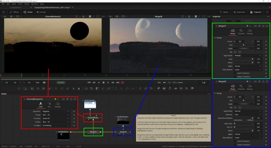
To use the chromatic alpha channel, you first need to multiply an inverted version of it over the non-Terragen background render element. Then merge any Terragen RGB render elements on top using Additive mode.
- Invert the chromatic alpha channel by adding a Channel Boolean node, with its Operation mode set to negative.
- Merge the inverted chromatic alpha channel with the non-Terragen render element, setting the Apply Mode to multiply.
- Merge the Terragen RGB render element, such as the tgRGB, in additive mode. In Fusion Studio, this means the Apply Mode = Normal, Operator = Over, and Alpha Gain = 0.
Data Elements[edit]
Terragen can also save render elements for data that is often used by compositors in order to create masks within the compositing software. Please be aware that each compositing package will have its own way of extracting the data.
Z-Depth[edit]
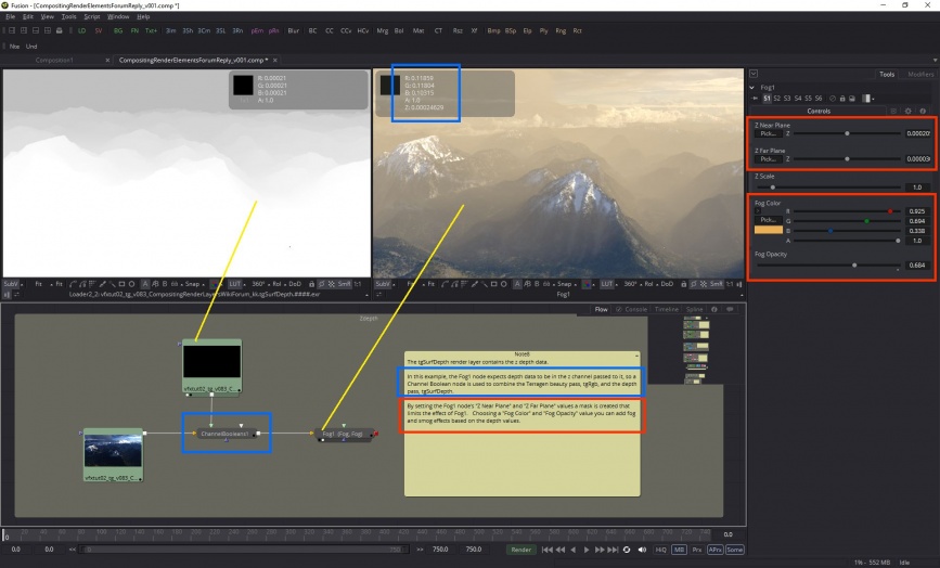
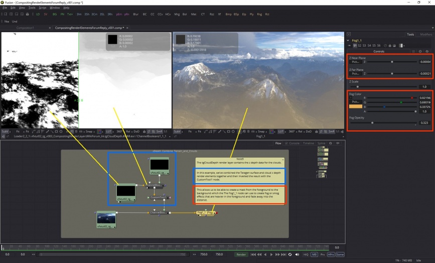
There are two depth render layers available, one for "Surface Depth" and the other for "Cloud Depth". This type of data is often referred to as a depth map or Z-depth. The data records the distance between the camera and an object or terrain, or a cloud.
In this example, I've added a layer of smog over the Terragen beauty pass render element by passing the data stored in the tgSurfDepth render element to the composting software's fog filter.
In this next example, the tgSurfDepth render element and the tgCloudDepth render element have been combined and passed along to the compositing software's fog filter to create a layer of smog in the foreground.
2d Motion[edit]
There are two motion vector render elements available, one for "Surface Motion" and the other for "Cloud Motion".
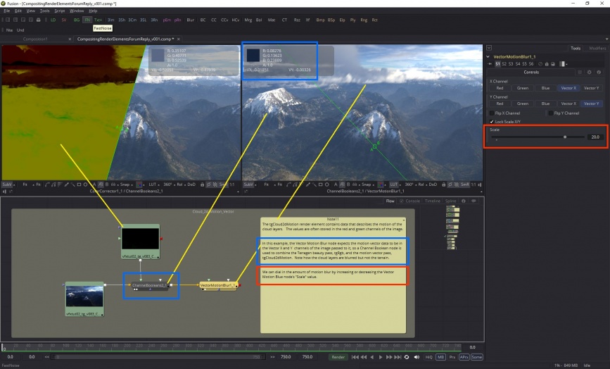
The "tgSurf2dMotion" render element contains data that describes the motion of objects within the image or frame. The X vector and Y vector values are stored in the red and green channels of the image. In CGI it's typically faster to render without realistic 3d motion blur, but by saving the 2d vector data an approximation of the motion blur can be made within the compositing software.
The "tgCloud2dMotion" render element contains data that describes the motion of the cloud layers within the image or frame. In the example below note how by using this render element we can isolate the cloud layers and apply 2d vector blur to only the cloud layers.
Position[edit]
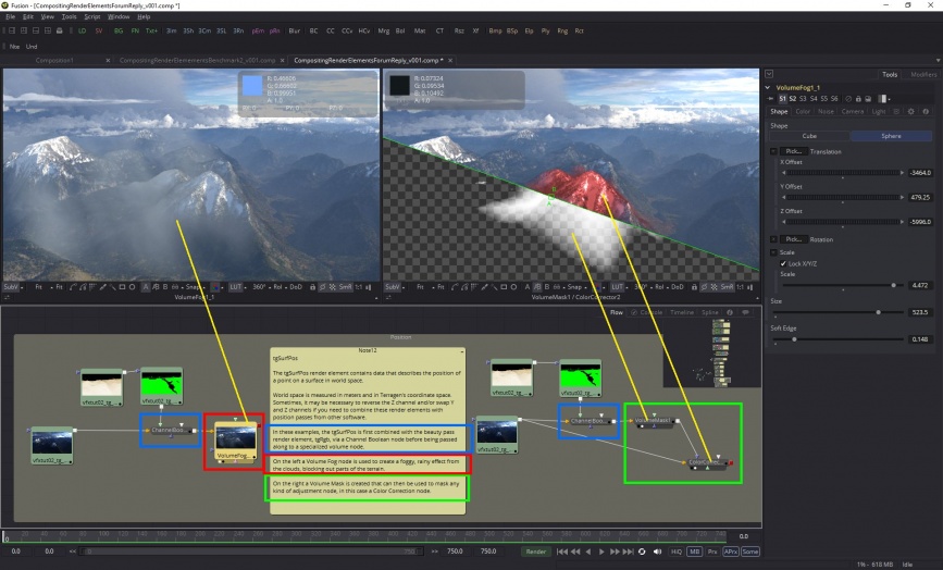
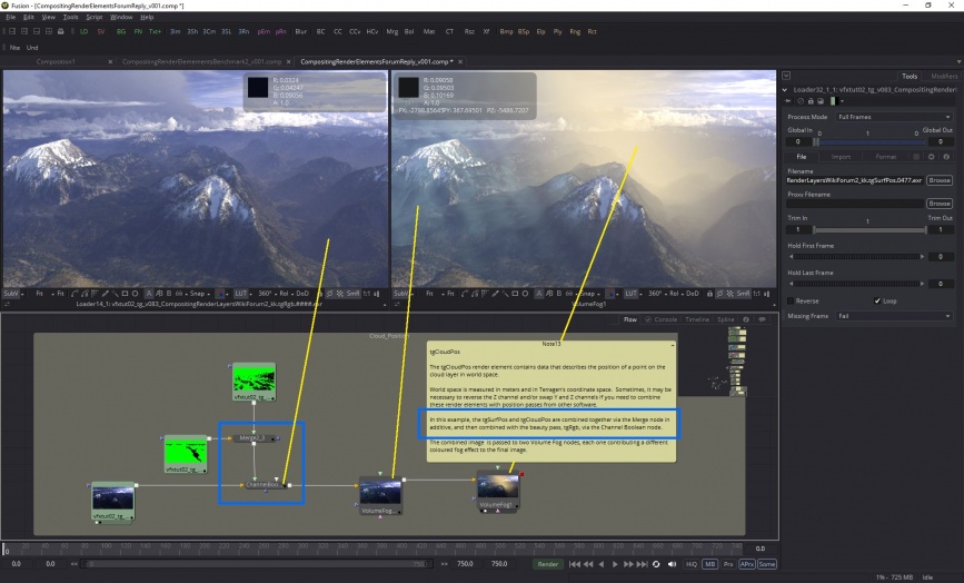
The “tgSurfPos” and “tgCloudPos” render elements contain data that describes the position of a point on a surface or cloud layer respectively, in world space. World position is measured in meters and in Terragen's coordinate space. Sometimes it may be necessary to reverse the Z channel and/or swap Y and Z channels if you need to combine the render element with position passes from other software.
Normals[edit]
The “tgSurfNormal” render element contains data describing the 3D vector of a line perpendicular to the surface of an object or terrain, in world space. Each pixel channel contains values from -1.0 to +1.0. The X Normals are mapped to the Red channel, and values below 0.0 to -1.0 indicate the underlying geometry is pointing in the direction of the -X axis in world space, while values above 0.0 to +1.0 point towards the +X axis. The Y Normals are mapped to the Green channel, and values lower than 0.0 point downward while values above 0.0 point upwards. The Z Normals are mapped to the Blue channel and values below 0.0 point towards the -Z axis, while values above 0.0 point towards the +Z axis in world space.
Depending on the compositing software being used, it may be necessary to reverse the Z channel and/or swap Y and Z channels if you need to combine the render element with normal passes from other software.
Surface Diffuse Colour[edit]
The "tgSurfDiffColor" render element contains an object or terrain's diffuse color values before any lighting is applied.
One way in which it can be used is to create masks based on the color values.
Sample Rate[edit]
The Sample Rate render element shows the distribution of “ray-traced subpixel samples” by the adaptive sampler. The colours represent a percentage of the maximum possible samples for a given anti-aliasing value. For example, 64 is the maximum possible samples for an anti-aliasing value of 8.
When viewing the image as an EXR, clamp the values at 1 (white) for ideal viewing. When clamped, the relationship of colour to the maximum possible samples is as follows:
- Fully white pixels = 100%
- Magenta pixels = 10%
- Blue pixels = 1%
- Black pixels = 0 samples.
Note, that although a pixel might contain no samples, interpolation occurs wherever samples are sparse.
When viewing as an unclamped EXR, the green channel goes from 0 to 1 to represent the fraction of samples, while the red and blue channels may exceed 1 as they are equal to the green channel multiplied by 10 and 100, respectively.
A single object or device in the node network which generates or modifies data and may accept input data or create output data or both, depending on its function. Nodes usually have their own settings which control the data they create or how they modify data passing through them. Nodes are connected together in a network to perform work in a network-based user interface. In Terragen 2 nodes are connected together to describe a scene.
A single element of an image which describes values for color and/or intensity, depending on the color system which the image uses. Groups of ordered pixels together form a raster image.
A vector is a set of three scalars, normally representing X, Y and Z coordinates. It also commonly represents rotation, where the values are pitch, heading and bank.
