Multiply Complement Colour
Overview[edit]
The Multiply Complement family of nodes allow you to multiply the colour/scalar coming into the Main Input by the complement of the color/scalar coming into Input 2.
The complement of a component value can be derived by subtracting the component value from the maximum possible value. For example, the pixel values in a greyscale image range from 0 - 255. The complement of a pixel value of 100 is 155. Likewise the complement of a pixel value of 0 is 255, and a pixel value of 255 is 0.
The multiplication is component-wise, for example with a colour:
-
Main Input.red multiplied by the complement of Input 2.red
Main Input.green multiplied by the complement of Input 2.green
Main Input.blue multiplied by the complement of Input 2.blue
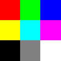
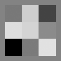
In the examples below, this image is used by the Image Map shader assigned to the Multiply complement colour’s Main input:
This example illustrates the effect of assigning greyscale colour values to Input 2 of the Multiply complement colour node. The complement of black is white, so there is no change to the value assigned to the Main input, whereas the complement of white is black, which results in black as the output. Grey values between white and black darken the values assigned to the Main input.
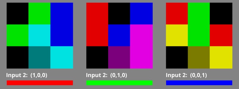
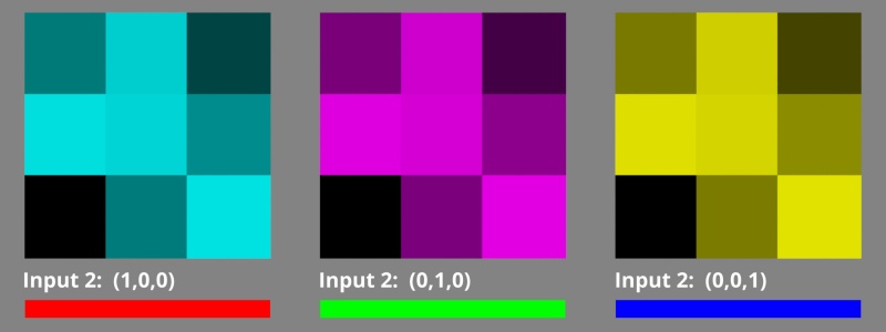
This example shows the effect of assigning red, green, or blue values to Input 2 of the Multiply complement colour node. Where the component values from the Main input and Input 2 are the same, black is the result.
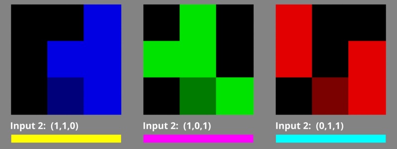
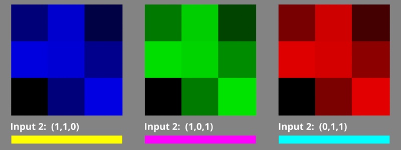
This example shows the effect of assigning secondary colours, yellow, magenta, or cyan to Input 2 of the Multiply complement colour node. Where the component values from the Main input and Input 2 are the same, black is the result.
In the examples below, this image is used by the Image Map shader assigned to the Multiply complement colour’s Main input
This example illustrates the effect of assigning greyscale colour values to Input 2 of the Multiply complement colour node. The complement of black is white, so there is no change to the value assigned to the Main input, whereas the complement of white is black, which results in black as the output. Grey values between white and black darken the values assigned to the Main input.
This example shows the effect of assigning red, green, or blue values to Input 2 of the Multiply complement colour node. Where the component values from the Main input and Input 2 are the same, black is the result.
This example shows the effect of assigning secondary colours, yellow, magenta, or cyan to Input 2 of the Multiply complement colour node. Where the component values from the Main input and Input 2 are the same, black is the result.
Settings:
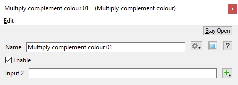
- Name: This setting allows you to apply a descriptive name to the node, which can be helpful when using multiple Multiply Complement Colour nodes in a project.
- Enable: When checked, the node is active and the multiplication operation will take place. When unchecked the values assigned to its Main Input, if any, are passed through, otherwise a value of 0 is passed through.
- Input 2: The component values from the shader or function nodes assigned to this setting are multiplied with those from the Main Input. When nothing is assigned, the Main Input values, if any, are passed through. If the Main Input is unassigned, the output from the node is 0.
A scalar is a single number. 1, 200.45, -45, -0.2 are all examples of scalar values.
A single element of an image which describes values for color and/or intensity, depending on the color system which the image uses. Groups of ordered pixels together form a raster image.
A shader is a program or set of instructions used in 3D computer graphics to determine the final surface properties of an object or image. This can include arbitrarily complex descriptions of light absorption and diffusion, texture mapping, reflection and refraction, shadowing, surface displacement and post-processing effects. In Terragen 2 shaders are used to construct and modify almost every element of a scene.
A single object or device in the node network which generates or modifies data and may accept input data or create output data or both, depending on its function. Nodes usually have their own settings which control the data they create or how they modify data passing through them. Nodes are connected together in a network to perform work in a network-based user interface. In Terragen 2 nodes are connected together to describe a scene.
