Vector Displacement - Terragen to Zbrush and back again
In this tutorial, we’ll explore how to make use of Terragen’s ability to import and export vector displacement data in order to harness the power of shaping and modifying terrain features that would otherwise be difficult to accomplish.
For example, heightfield maps are great for displacing surfaces based on height or elevation data, but not so great at creating overhangs. Vector displacements can accomplish this, because in addition to Y axis, or height/elevation data, they contain a sample point’s position data for the X axis and Z axis.
A vector displacement workflow also allows you to create and modify data between different 3D software packages, and for this tutorial we’ll focus on exporting and importing vector displacement information to and from Zbrush.
Additionally, you may discover that complex Terragen terrains, such as those with overhangs and lateral displacements, may render significantly faster by making use of the Vector Displacement shader than by simply rendering the project using a normal procedural workflow.
For demonstration purposes, we’ll create a very simple terrain feature using a Simple shape shader, augmented with a Fake stones shader to provide some overhanging data, and output this as a vector displacement image. We’ll import this image into Zbrush and make some modifications, then export those results as a vector displacement image. Finally, we’ll import the modified image back into Terragen and compare it to the original displacements.
Let’s get started!
Create a procedural terrain in Terragen[edit]
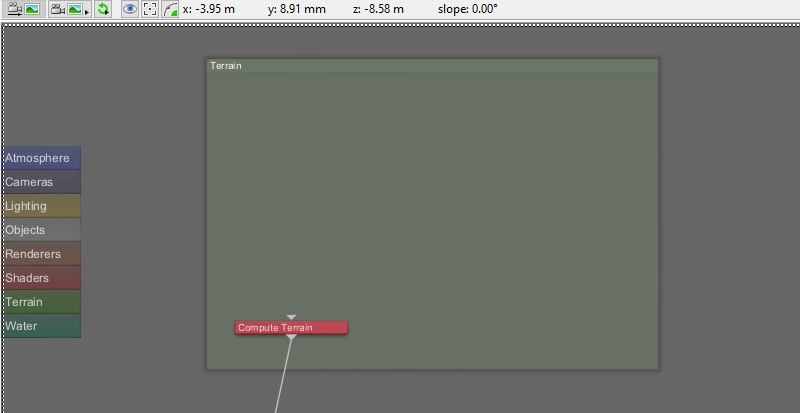
Starting with the default Terragen project, we’ll remove all the displacements to the terrain, in order to leave a completely smooth and non-displaced planet surface.
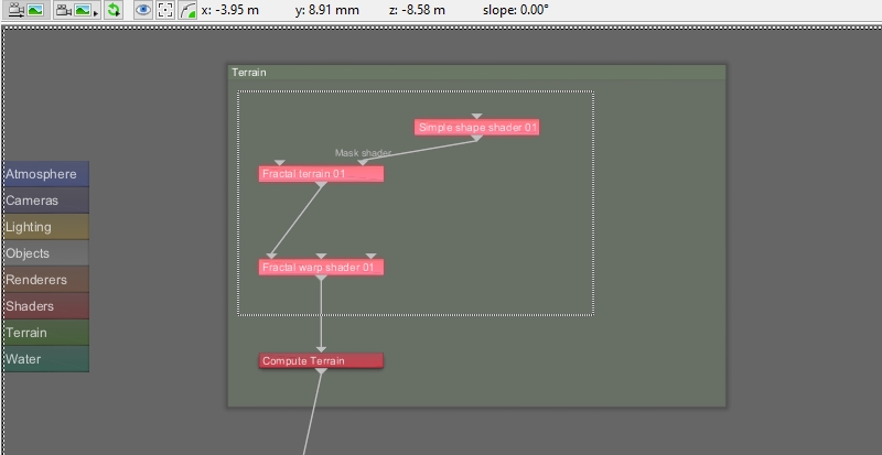
- In the Node Network pane, left-click and drag a selection box around the “Fractal warp”, “Fractal terrain”, and “Simple shape” shader nodes.
- Press the delete key.
Without the visual reference that a displaced terrain provides, it can be difficult to determine a location or scale in the project, so we’ll add a Landmark object at the origin of the scene for reference.
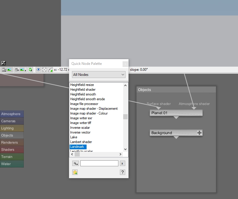
- Press the tab key or “N” key on your keyboard to open the Quick Node Palette window.
- Start typing the word “Landmark” and the closest match in the Node List will become highlighted.
- With “Landmark” highlighted, press the enter key to add it to the project.
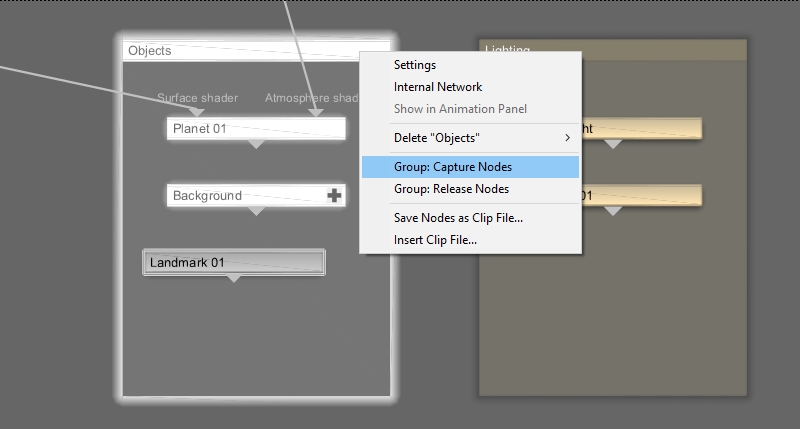
When you manually add a node to a group, it’s a good idea to capture all the nodes in the group.
- Right-click the “Object group“ node.
- Select “Group: Capture Nodes”.
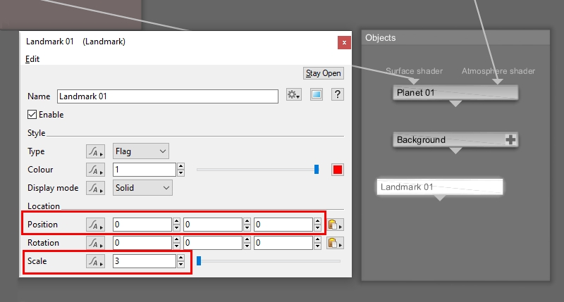
Position the Landmark at the origin of the project, and then scale it to an appropriate size for the terrain or task you are doing. Since we’re creating a relatively small rock pile, the size of the Landmark does not have to be extremely large.
- Double-click the “Landmark” node to open its window.
- Set "Position > 0,0,0"
- Set "Scale > 3"
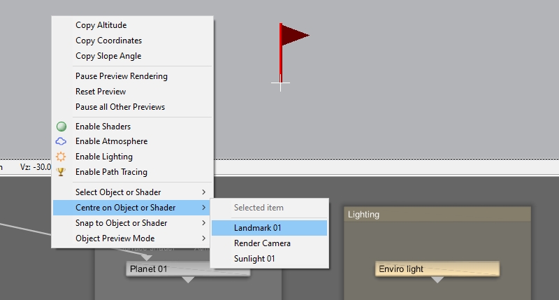
You can automatically center the 3D Preview on any enabled item in the project.
- Right-click in the 3D Preview pane.
- Select “Centre on Object or Shader > Landmark 01”
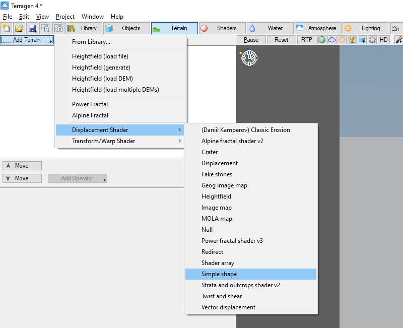
Let’s displace a small mound near the origin of the project.
- Click the “Terrain'” button beneath the main menu.
- Click the “Add Terrain” button.
- Select “Displacement Shader > Simple shape”.
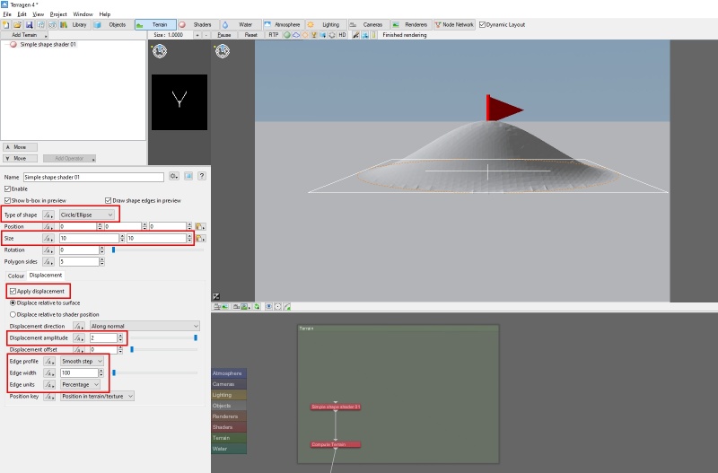
After we define the size and shape of the shader, we can use it to displace the terrain. These settings will result in a soft sloping mound at the origin of the scene.
- In the Terrain Node list, select “Simple shape shader 01”.
- Click the “Colour” tab.
- Select “Type of shape > Circle/Ellipse”.
- Set “Size > 10 (metres)”.
- Click the “Displacement tab.
- Check “Apply displacement”.
- Set “Displacement amplitude > 2 (metres)”.
- Select “Edge profile > Smooth step”.
- Set “Edge width > 100”.
- Select “Edge units > Percent”.
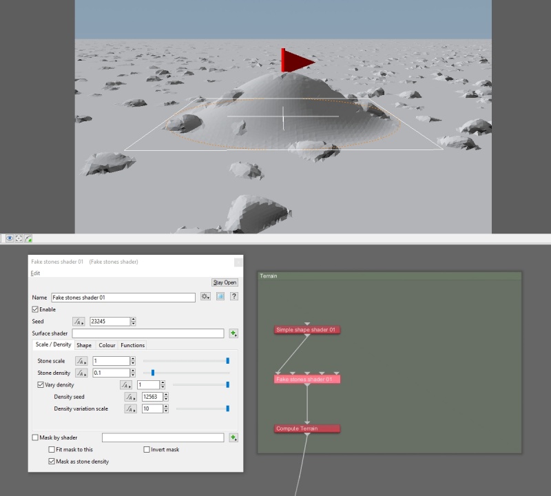
We can change the appearance of the mound to a pile of rocks with the addition of a Fake Stone shader.
- In the Node Network pane, right-click the “Simple shape shader” node.
- Select “Displacement Shader > Fake stones”.
The Fake Stone shader’s default settings randomly populate rocks across the entire terrain.
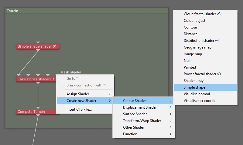
We can restrict the rocks to just the mound area by assigning another Simple Shape shader as a mask to the Fake Stones shader.
- In the Node Network pane, right-click the “Fake Stones shader” node’s “Mask shader input”.
- Select “Create new Shader > Colour Shader > Simple Shape”.
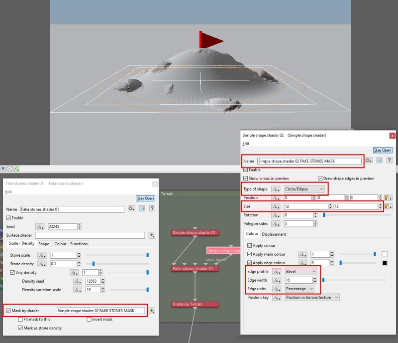
Rename the node so that it’s easier to identify in the project, then apply the settings below to create a colour mask that’s slightly larger than the mound, which will allow the rocks to extend a bit onto the flat ground.
- Double-click the “Simple shape shader" node to open its dialog window.
- Rename “Name > Simple shape shader 02 FAKE STONES MASK”.
- Select “Type of shape > Circle/Ellipse”.
- Set “Size > 12 (metres)”.
- Select “Edge profile > Bevel”.
- Set “Edge width > 15”.
- Select “Edge units > Percentage”.
- Close the “Simple shape shader" window.
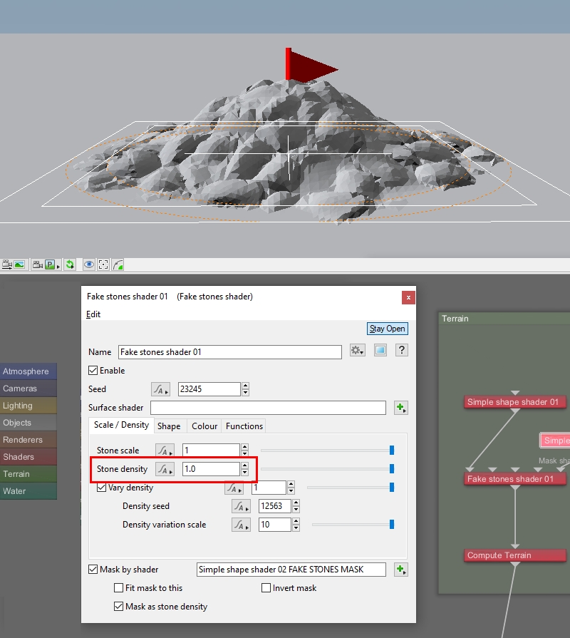
The amount of rocks is controlled by the Fake stones shader’s “Stone density” parameter. When a value of 1.0 is used, the entire masked area will be covered with rocks. Let’s do that.
- Set “Stone density > 1.0”
Now that we have a pile of rocks with some overhanging features, we can set up Terragen to render an image suitable for vector displacement.
First, we need to convert the terrain’s displacement data to vector data, and we can do that by adding a “Displacement shader to vector” node to the project.
- Press tab, to launch the Quick Node Pallette.
- Select “Displacement shader to vector” and press enter.
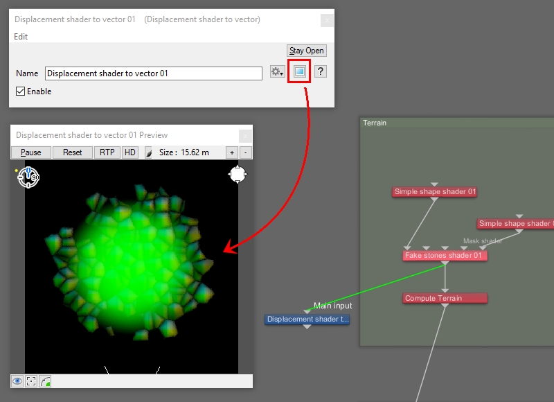
We want to connect this node to the last displacement node used to sculpt the terrain shape, which is the Fake stones shader node. Once connected, open the shader’s preview window to display the vector data as colour values. The red and blue channels contain the X and Z axis data respectively, and the green channel contains the Y axis, or elevation, data.
- In the Node Network pane, drag a connection line from the “Fake stones shader" node’s “Output” to the “Main input” of the “Displacement shader to vector” node.
- Double-click on the “Displacement shader to vector” node to open its dialog window.
- Click on the “Open shader preview in new window” button.
At the time of this writing, vector displacement maps are not yet standardized across different 3D software packages and applications. While our vector displacement data is correct for use in Terragen, we might need to modify the data so that it appears the same in another software application.
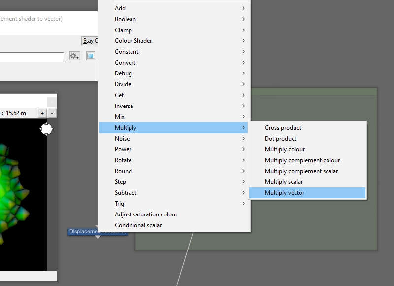
Adding a “Multiply vector” node after the “Displacement shader to vector” node will allow us to fine tune the vector data if necessary, prior to rendering the final vector displacement image for use in another software package..
- Right-click the “Displacement shader to vector“ node.
- Select “Multiply > Multiply vector”.
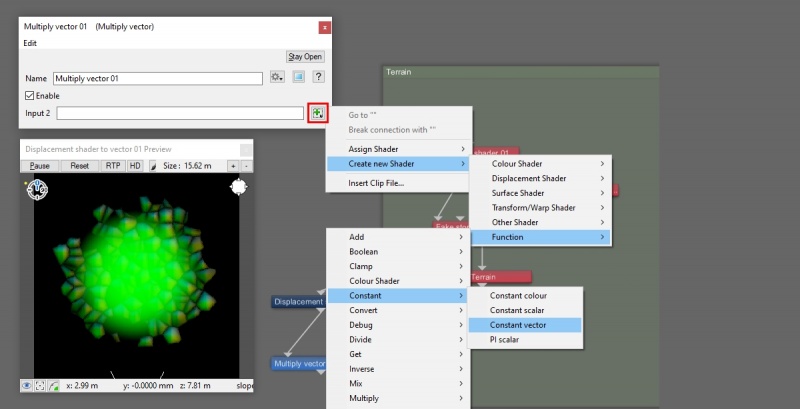
The “Multiply vector” node takes the incoming vector data for each component assigned to its “Main input” and multiplies them by the values assigned in its “Input 2” setting. Shader or function nodes may be assigned to “Input 2”. We’ll add a “Constant vector” node in order to modify the vector data as needed.
- Double-click the “Multiply vector” node to open its dialog window.
- Click the green “Plus” button to the right of the “Input 2'” parameter.
- Select “Create new Shader > Function > Constant > Constant vector”.
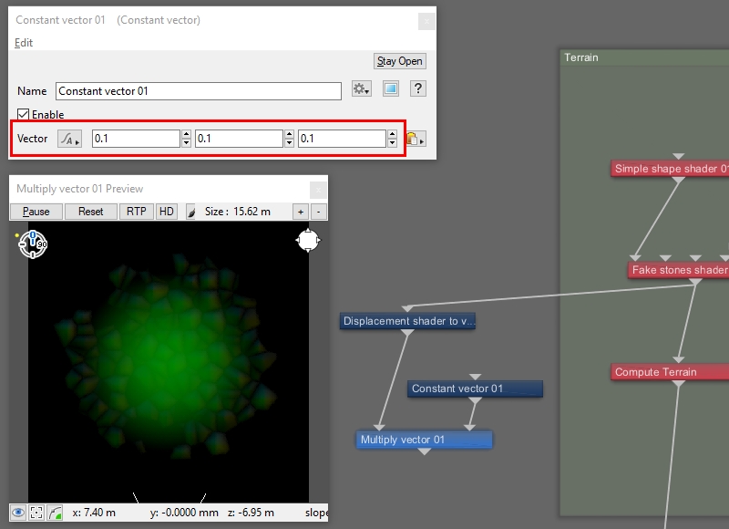
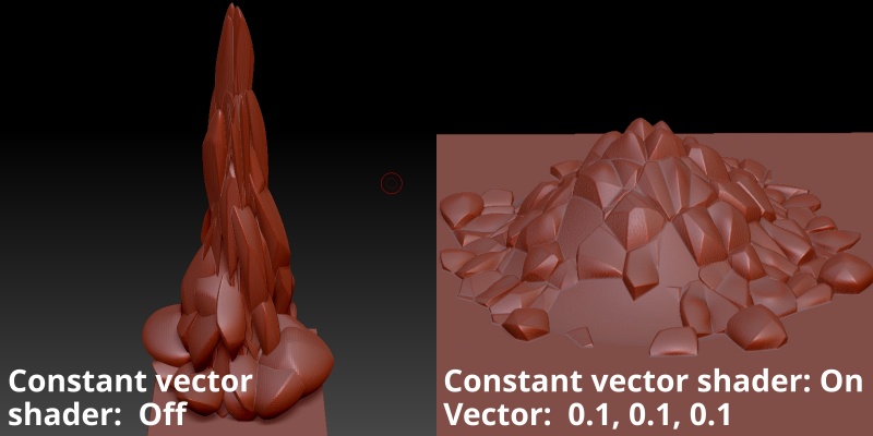
In Terragen the default unit equals one metre. For this tutorial, we’ll import the final vector displacement image into Zbrush, whose unit is equal to one centimeter, so we’ll reduce the vector displacement data appropriately. Notice in the shader preview window how the colour values darken based on the Constant vector’s values.
- Double-click the “Constant vector” node to open its dialog window.
- Set “Vector > 0.1, 0.1, 0.1”.
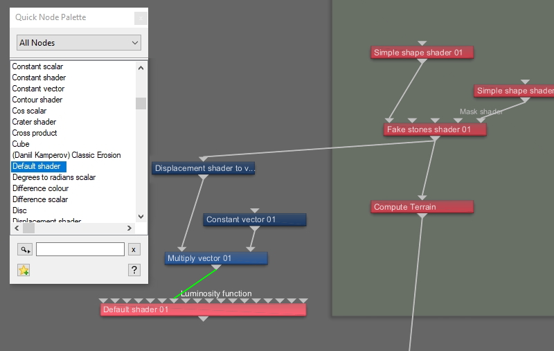
Next we need to output this data to a shader so that it can be rendered as an image. We’ll use a Default shader to do that, connecting the output from the “Multiply vector” node to the “Luminosity function” input of the “Default shader” node.
- Press tab, to launch the Quick Node Pallette.
- Select “Default shader” and press enter.
- Drag a connection line from the “Output” of the ”Multiply vector” node to the “Luminosity function” input of the “Default shader” node.
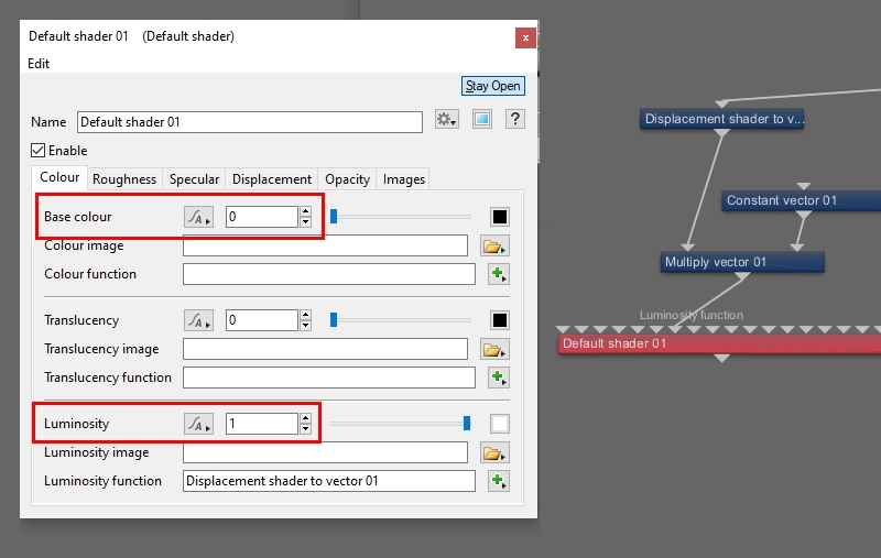
We want the Default shader to respond only to the vector data supplied through its Luminosity function, so we need to disable any other parameter that might contribute to its final look.
- Double-click the “Default shader” to open its dialog window.
- Set “Base colour > 0”.
- Set “Luminosity > 1”.
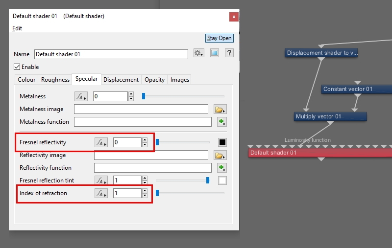
On the Specular tab, make sure the shader receives no reflection or refraction from the environment.
- Click the “Specular“ tab.
- Set “Fresnel reflectivity > 0”.
- Set “Index of refraction > 1”.
Now we need to connect the Default shader to a surface so that it can be rendered. In order to do that we’ll duplicate the Planet node that’s located in the Object group. In this way, we preserve the planet’s curvature and other settings such as its radius and position.
- Left-click on the “Planet” node to select it.
- Press “Ctrl+D/Cmd+D” on your keyboard to duplicate the Planet node.
- Drag a connection line from the “Output” of the ”Default shader” node to the “Surface shader“ input of the duplicated Planet node.
These next steps allow us to have two renderers in the project and switch between them at will. One for viewing and rendering the vector displacement surface, and one for our normal perspective view. If we want to make modifications to the terrain we can do so while using the perspective view, then switch to the vector displacement view and render those changes.
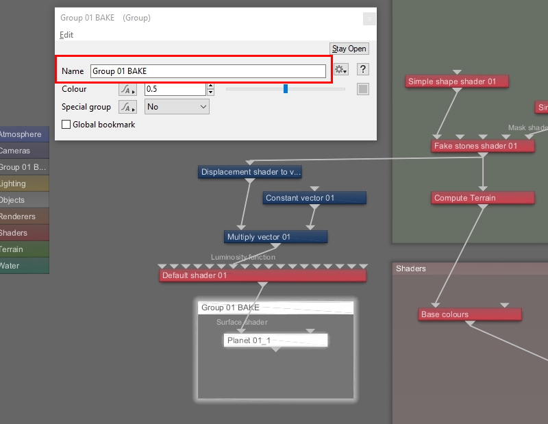
First we’ll group the new Planet node to itself, in order to assign the group to a render layer later on, and give it a descriptive name so that it’s easy to identify.
- Left-click on the duplicated “Planet” node to select it.
- Press “Ctrl+G/Cmd+G” on your keyboard to group the node to itself.
- Double-click on the new “Group 01” to open its dialog window.
- Set “Name > Group 01 BAKE”.
- Close the group dialog window.
Next, add a new camera to the project, which we’ll use for the new renderer we’ll create in just a moment.
- Click the “Cameras” button on the toolbar.
- Click the “Add Camera” button.
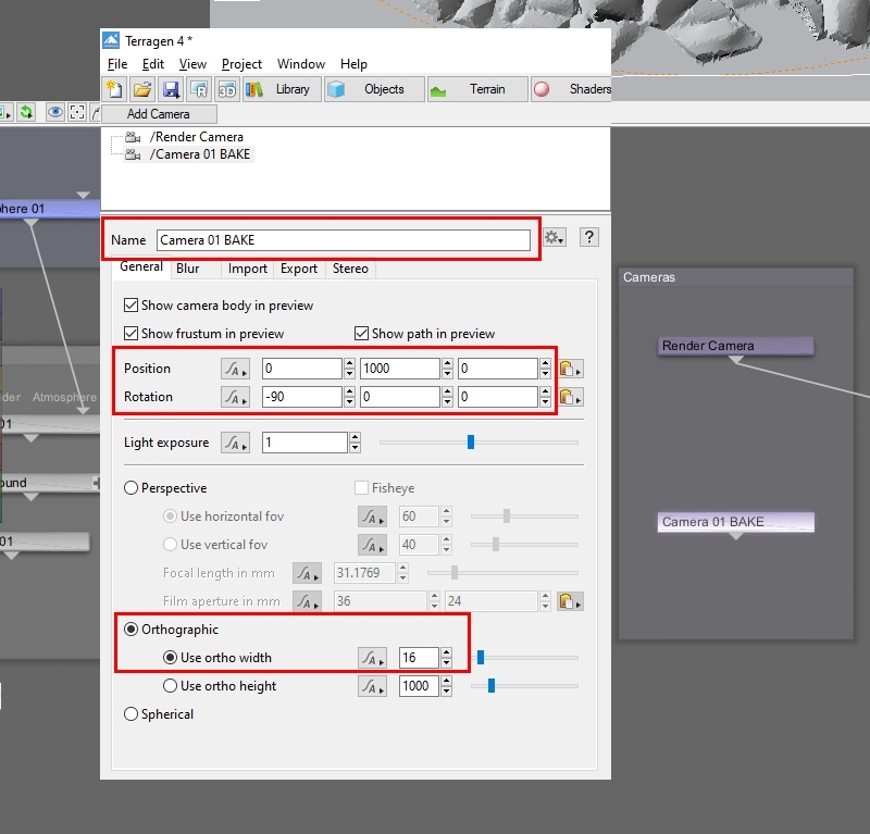
We need to position and rotate the camera so that it’s higher than any terrain features and pointed down at the terrain, then we can change it to an orthographic camera which will allow us to define the size in metres of the terrain we wish to capture, as well as to eliminate any perspective from the camera’s point of view. The rock pile covers about 10 metres, so we'll set the orthographic camera’s width to be slightly larger. It’s also a good idea to rename the camera so that it’s easy to identify later on.
- Set “Name > Camera 01 BAKE”.
- Set “Position > 0, 1000, 0”.
- Set “Rotation > -90, 0, 0“.
- Check “Orthographic”.
- Set “Use ortho width > 16”.
Now add a new renderer to the project. We’ll use this to render the vector displacement image.
- Click the “Renderers” button on the toolbar.
- Click the “Add Renderer” button.
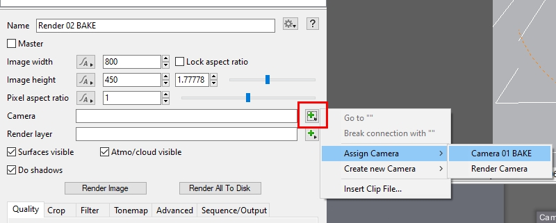
Then assign the orthographic camera to the renderer.
- Click the green “Plus” button to the right of the “Camera” label.
- Select “Assign Camera > Camera 01 Bake”.
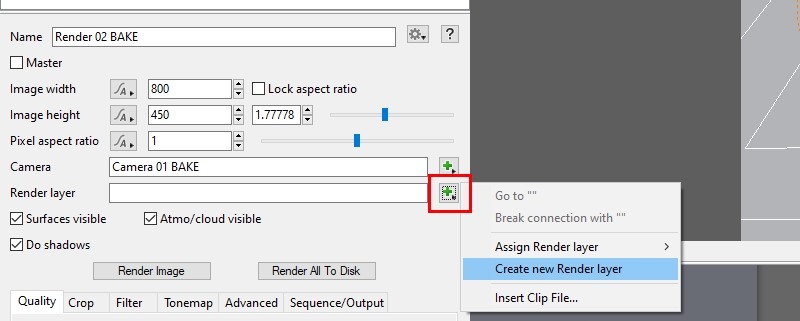
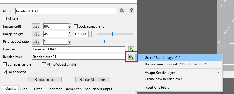
The Render Layer feature in Terragen 4 Professional allows us to select which groups of objects will actually render and how they are seen by the renderer. For the render of the vector displacement data we’ll hide everything except the duplicated planet node. Start by creating a new render layer.
- Click the green “Plus” button to the right of the “Render layer” label.
- Select “Create new Render layer”.
Once created, goto the Render layer to open up its dialog window.
- Click on the green “Plus” button to the right of the “Render layer” label.
- Select “Go to “Render layer 01””
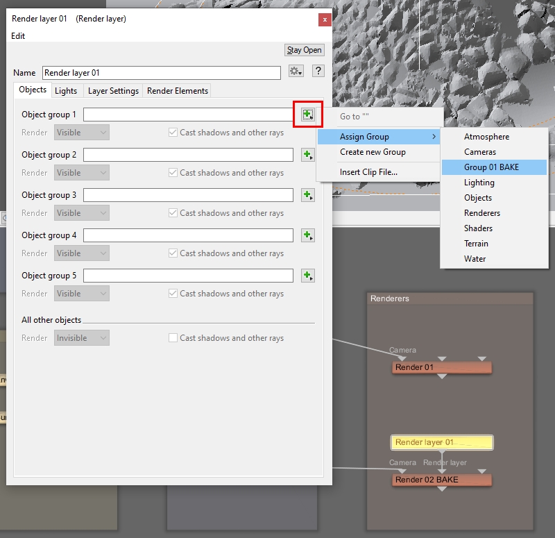
Now we can assign the group containing the duplicated Planet node to the Render layer.
- Click the green “Plus” button to the right of the “Object group 1” label.
- Select “Assign Group > Group 01 BAKE”.
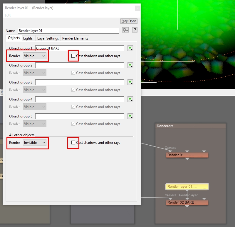
We want this render group to show up in the render and everything else to be invisible, so set its render mode to be visible, and for the “All other objects” group to be invisible. Since we only want the luminosity values of the Default shader to show up in the render, make sure that “Cast shadows and other rays” are unchecked for all groups.
- Select “Object group 1 > Render > Visible”.
- Select “Object group 1 > Cast shadows and other rays > Unchecked”.
- Select “All other objects > Render > Invisible”.
- Select “All other objects > Cast shadows and other rays > Unchecked.”
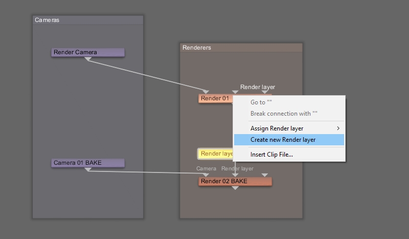
While we’re creating Render layers, let’s make one for the default renderer in the project, which we’ll use as our perspective camera in order to view the project as we normally do.
- Right click the “Render layer” input for the “Render 01” node.
- Select “Create new Render layer”.
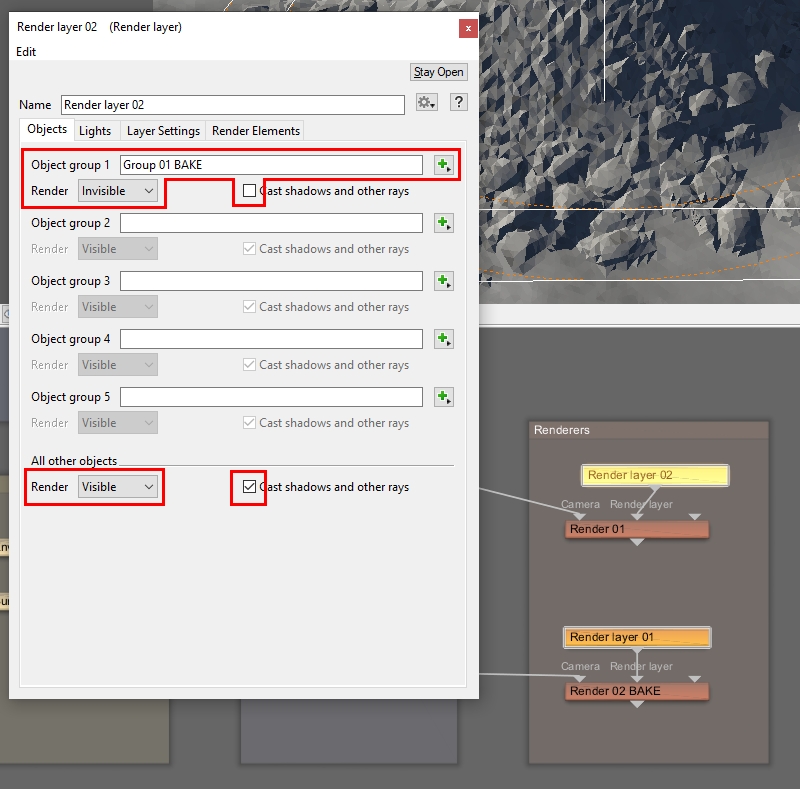
Whenever we switch to this renderer we don’t want to see the duplicated Planet and its luminosity coloured surface, just the normal terrain with the rock pile. Open the Render layer’s dialog window and assign the duplicated Planet group just as before. Then set it to be invisible and not cast shadows or rays, while everything else is visible and casting shadows and rays.
- Double-click the new “Render layer 02” node to open its dialog window.
- Click on the green “Plus” button to the right of the Object group 1 label.
- Select “Assign Group > Group 01 BAKE”.
- Select “Object group 1 > Render > Invisible”.
- Select “Object group 1 > Cast shadows and other rays > Unchecked”.
- Select “All other objects > Render > Visible”.
- Select “All other objects > Cast shadows and other rays > Checked”.
Now we just need to set up the render settings for the renderer itself.
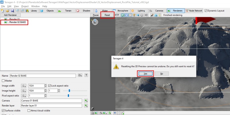
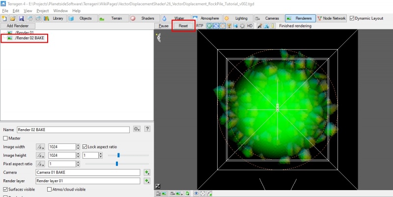
Terragen makes it easy to switch between the different renderer views in the 3D Preview. Just select a renderer in the Render Node List and click on the “Reset” button below the toolbar. If the “Resetting the 3D Preview” warning message appears, just click “Yes”. Terragen will update the 3D Preview pane with the view from the camera assigned to the renderer.
Select the renderer you wish to view.
- Click the “Reset” button.
- Click the “Yes” button, if a warning message appears.
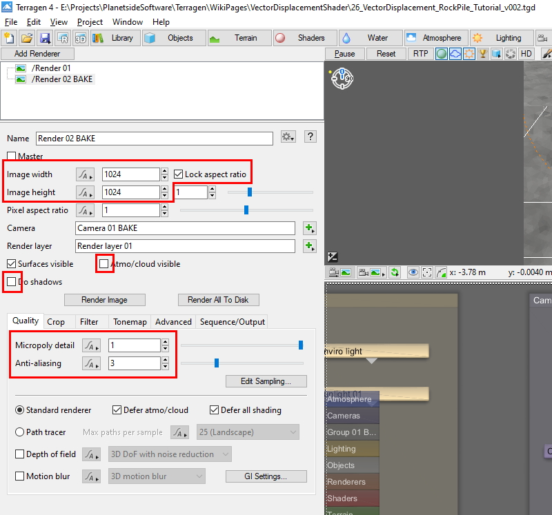
Many 3D applications expect the vector displacement map to be a square image, so set the Image width and height parameters to the same value. For test renders you might try values like 512 x 512, or 1024 x 1024 because these smaller images will render faster, although there will also be less detail.
As previously mentioned, we want the render to only contain the luminosity values of the planet surface, so uncheck the renderer’s “Atmo/Cloud visible” and “Do shadows” checkboxes.
The “Micropoly detail” parameter controls the level of detail seen by the renderer. For test purposes, you can use low values but for final render set the value to 1.
The use of anti-aliaing can greatly increase both the quality and time it takes to render the image. Low values are good for testing, but use higher values for the final render.
- Set “Image width > 1024“.
- Set “Image height > 1024”.
- Uncheck “Atmo/Cloud visible”.
- Uncheck “Do shadows”.
- Set “Micropoly detail > 1.0”.
- Set “Anti-aliasing > 3”.
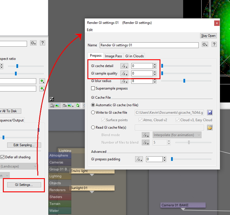
For the same reason we disabled the “Atmo/Clouds visible” and “Do shadows” checkboxes, we can turn off global illumination for the project. Under the “GI settings” button turn off the “GI Cache detail” and “GI sample quality” by setting them to zero.
- Click the “GI Settings” button to open its dialog window.
- Set “GI cache detail > 0”.
- Set “GI sample quality > 0”.
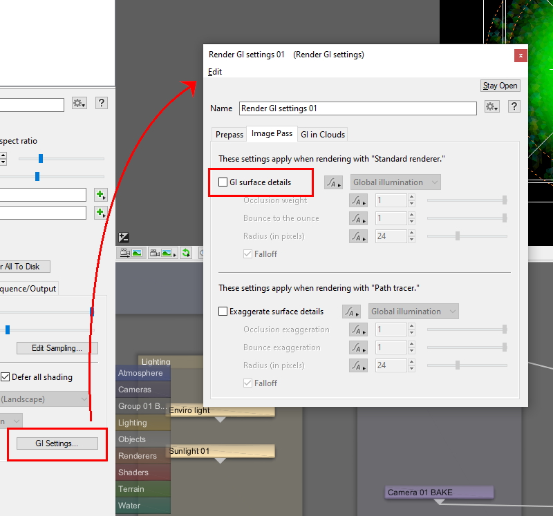
Under the Image Pass tab, disable the “GI surface details”, so as not to introduce additional shading to the rendered image.
- Click the “Image Pass” tab.
- Uncheck “GI surface details”.
- Close the “GI settings” dialog window.
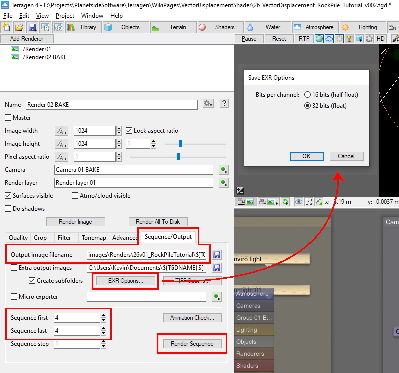
The vector displacement image needs to be saved as a 32 bit EXR file. Under the Sequence/Output tab, use the settings below to configure the file saving parameters, and then you’re ready to render the vector displacement image.
- Click the “Sequence/Output” tab.
- Click the blue “Save as” button to the right of the “Output image filename” setting.
- Set “Output image filename > To whatever filename you want to use”.
- Select “Save as type > OpenEXR (*.exr)”.
- Click the “EXR Options” button to open its dialog window.
- Check “Bits per channel > 32 bits (float)”.
- Set “Sequence first > The first frame you want to render”.
- Set “Sequence last > The last frame you want to render”.
Import into Zbrush[edit]
Now we’ll import the rendered vector displacement image into Zbrush. Launch the Zbrush application.
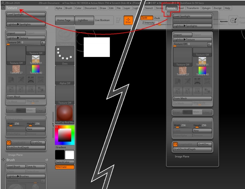
In Zbrush, you can dock any of the tool palettes to the trays at the left, right and bottom of the screen. Docking the Texture palette on the left side of the main interface will make it readily accessible to us throughout the project.
- Click on the "Texture menu option to open the Texture palette window.
- Click the "Palette icon and drag the window to the left side of the interface.
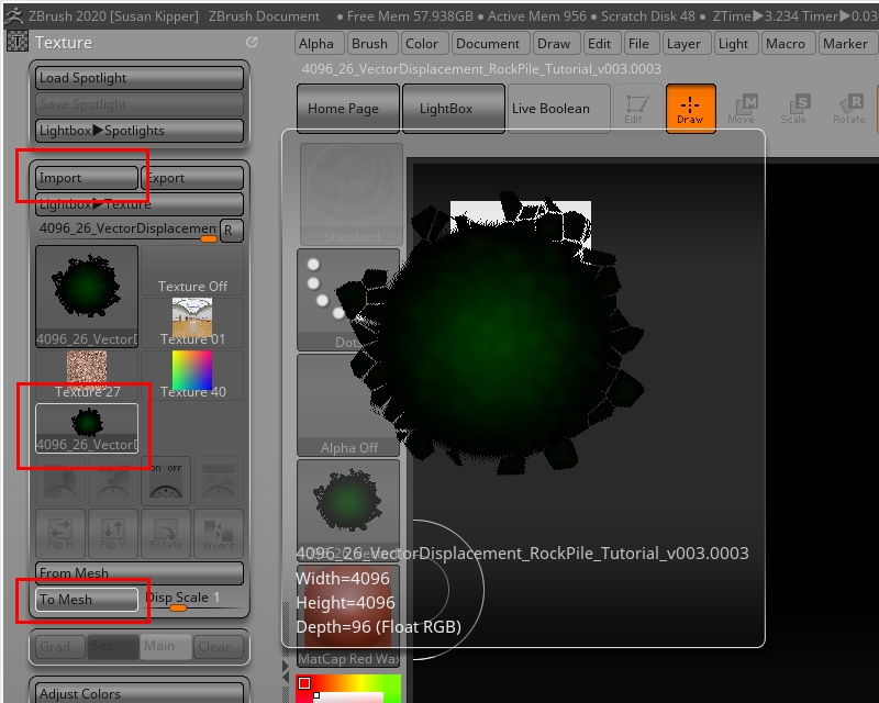
Now we can import the vector displacement image we created in Terragen. Once imported, its thumbnail image will appear in the image list. Selecting it in the list will display its name, resolution and depth information. To convert the image into a mesh, click the “To Mesh” button.
- Click on the “Import” button.
- Navigate to the location of the saved EXR file and import it.
- Click on the image thumbnail.
- Click on the “To Mesh” button.
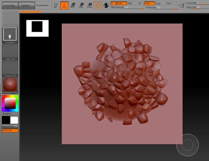
For the mesh to appear in the canvas area, you need to click and drag out its shape. It’s important to understand that even though the geometry looks three dimensional at this point, Zbrush only sees it as 2.5D, which means that you can’t treat it like geometry yet.
- Click and drag anywhere in the canvas to drag out the shape.
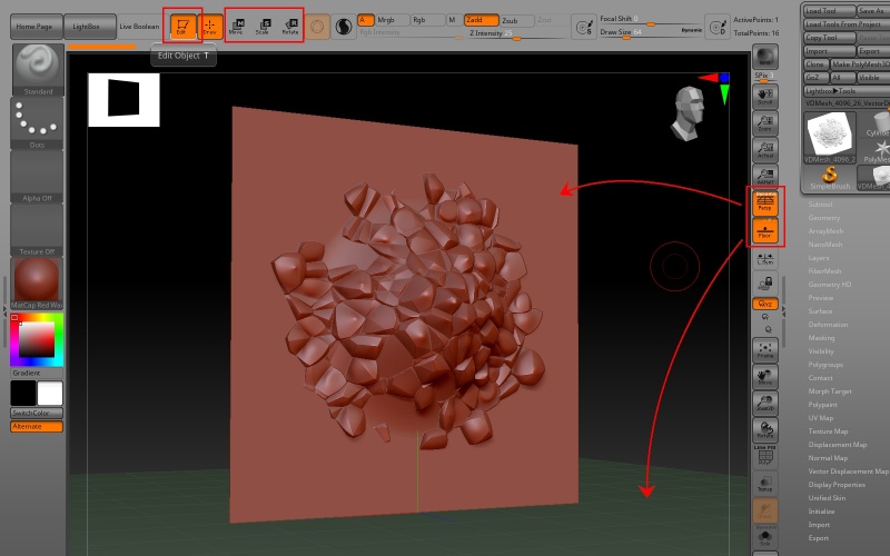
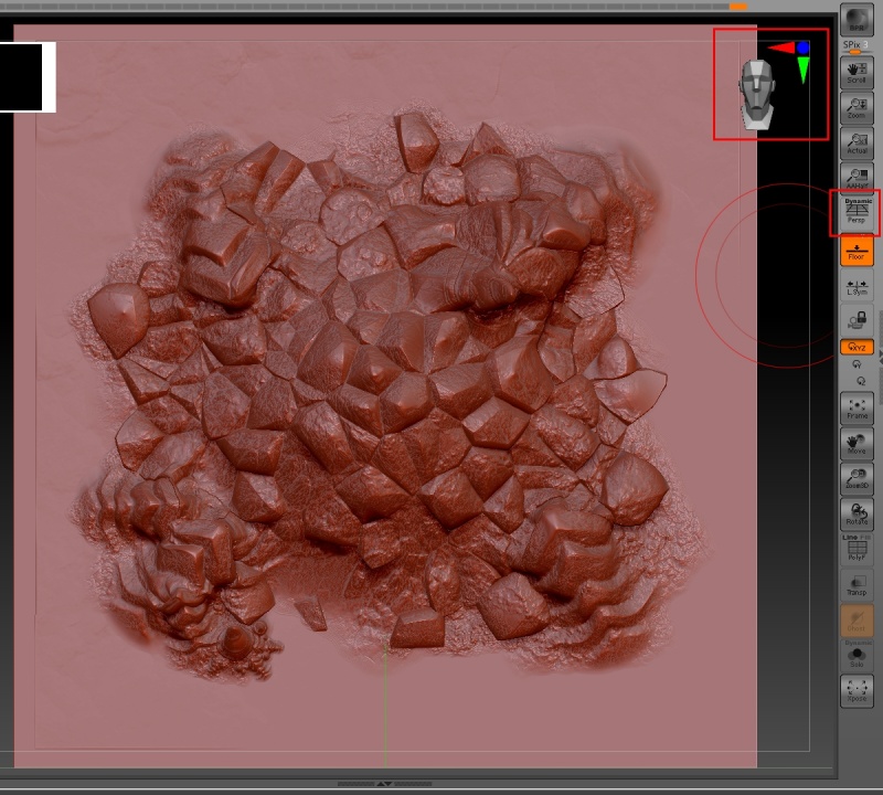
To convert the 2.5D data to 3D, click the “Edit” button. Zbrush now understands this as a 3D mesh. You can move, scale, and rotate the mesh with the three buttons at the top, or use mouse and keyboard combinations to do the same. It can also be helpful to enable the grid plane and the dynamic perspective view by clicking on their buttons to the right of the canvas area.
- Click the "Edit" button.
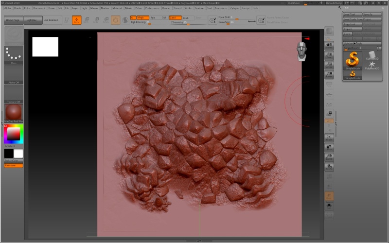
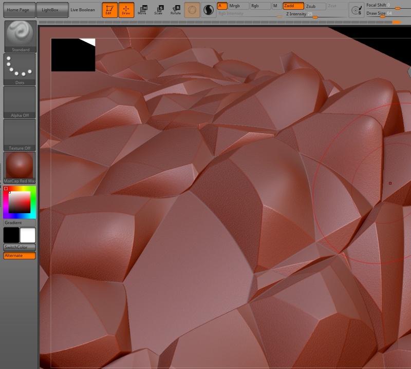
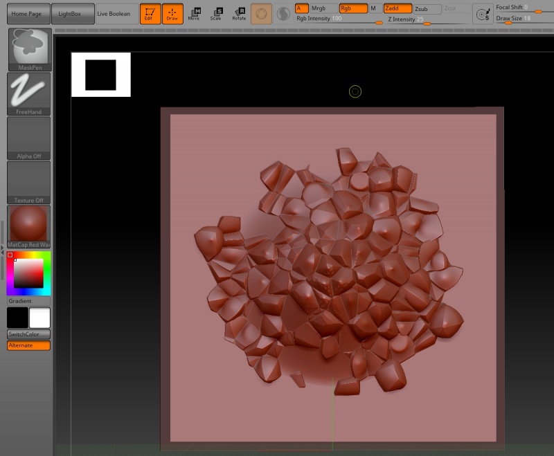
Here’s a closeup of the unmodified vector displacement image converted to a mesh in Zbrush. The vector displacement image resolution is 4096 x 4096, and the Fake stones detail is well preserved.
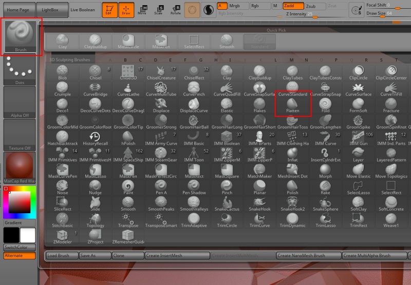
There are many tools in Zbrush for modifying a mesh. You can access any of the brushes, strokes, or alpha images by clicking on the appropriate thumbnail. Let’s start by replacing the default “Standard” brush with a “Flatten” brush in order to reduce the hard edges along the Fake stones.
- Click on the “Brush” thumbnail to open the brush pop-up menu.
- Select “Flatten” brush thumbnail.
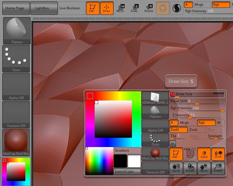
If the size of the brush appears to be large or small, you can adjust its attributes by pressing the space bar on your keyboard which will bring up an interface window where you can use the sliders to adjust the size. We want to use a small to medium sized brush to modify the edges of the Fake stones.
- Press “spacebar”.
- Adjust brush attributes with sliders.
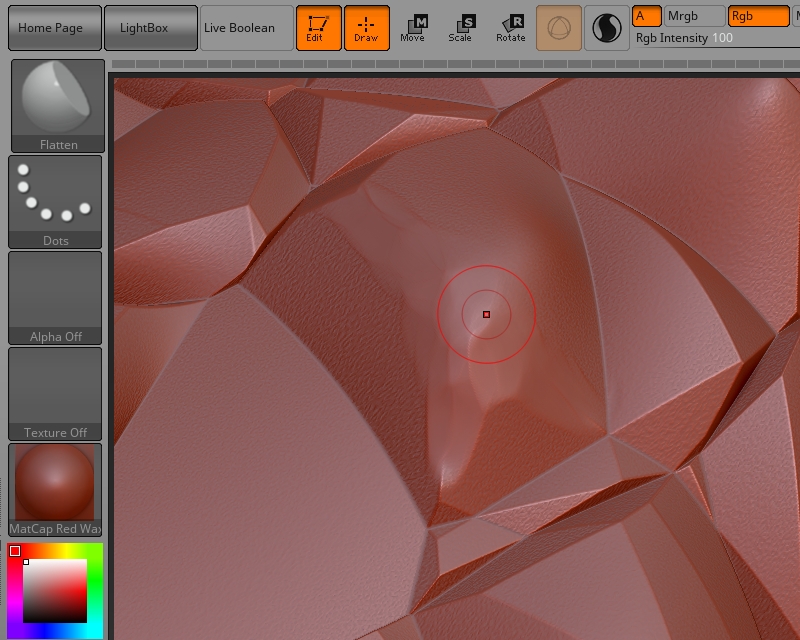
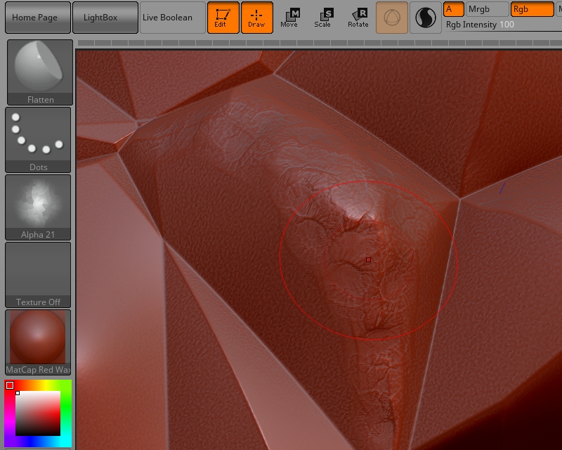
To activate the brush and begin sculpting the geometry, click and drag along the edges of the Fake stones. While this can breakup and soften the hard edge, it doesn’t provide for much variation.
- Click and drag along the hard edges of the Fake stones.
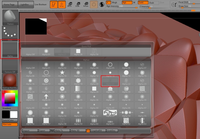
By assigning an alpha image to a 3D brush we can introduce variation into the sculpting properties of the brush.
- Click the “Alpha” thumbnail to open the Alpha pop-up menu.
- Select an alpha image.
Now when you click and drag along the edges of the Fake stones, you will see some variation and randomness due to the alpha image as the hard edges are reduced.
Here’s an example showing some of the hard edges along the Fake stones knocked down a bit.
Ideally, we don’t want to perturb the edges of the mesh, so that their vertices remain flat. This will allow the final results of our Zbrush deformations to seamlessly blend into the terrain when re-imported back into Terragen. Just like in Terragen, Zbrush has the ability to mask an area so that it remains unaffected by a sculpting operation. You create a mask in Zbrush by pressing the “Ctrl” key while left-clicking and dragging around the canvas or mesh. The mask will appear as a darker colour on the mesh.
- Hold the “Ctrl” key while left-clicking and dragging a bounding box around each edge of the geometry, one at a time.
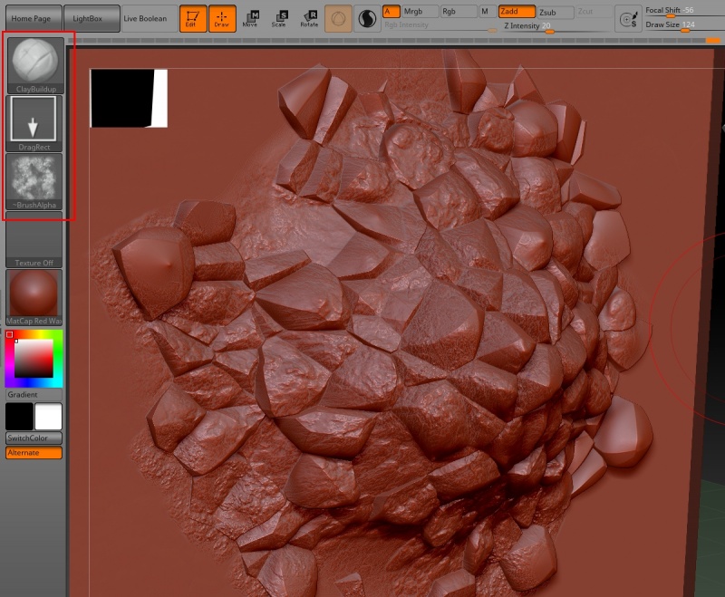
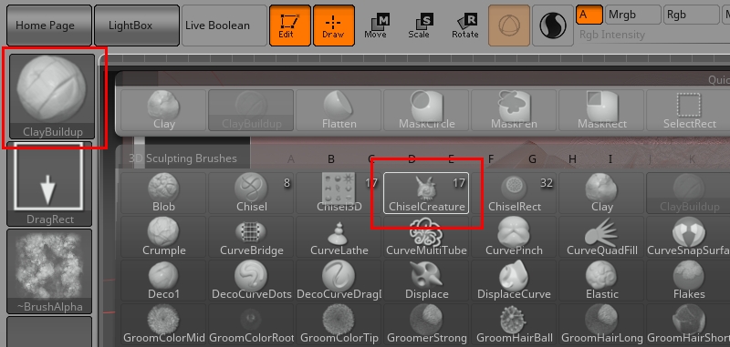
With the edges now protected, you can choose any brush, stroke and alpha image to create detail on the mesh. For this tutorial, we’ve selected the “Clay buildup” brush, a “Drag Rectangle” stroke, and a rock-type alpha image. Once the brush is set up to your liking, click and drag around the mesh to displace its surface and build up the detail.
In addition to these standard-type brushes with alpha images, Zbrush has several “Chisel” brushes, which contain vector displacement meshes. These allow you to sculpt vector based shapes onto your mesh. Choose one of the chisel brushes.
- Click the “Claybuildup” brush thumbnail to open the brush palette.
- Click the “ChiselCreature” brush.
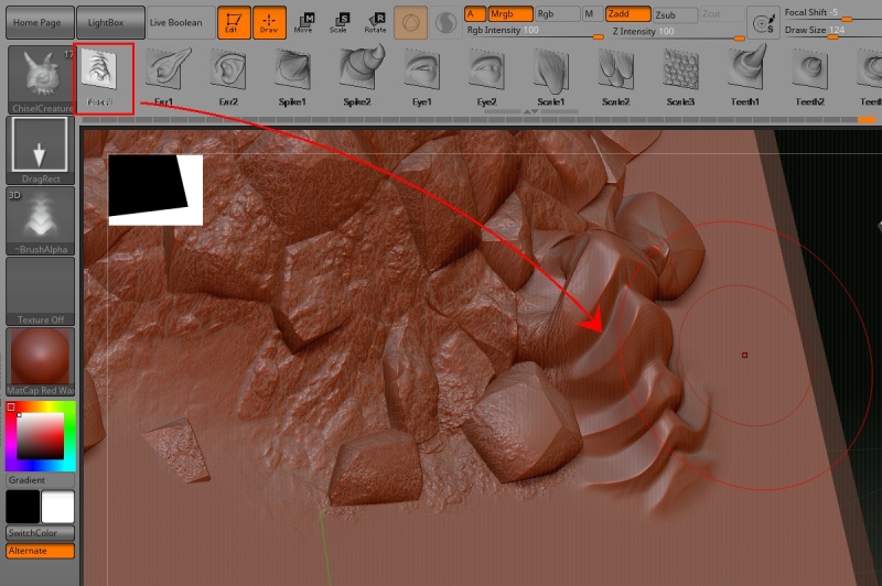
When you select a chisel brush, you’ll see a series of subtool meshes along the ribbon at the top. When you select one by clicking on it, the stroke type and alpha image thumbnails will update. Just as with the previous brush type, click and drag along the mesh to insert the shape. You can rotate and scale the shape while dragging it out.
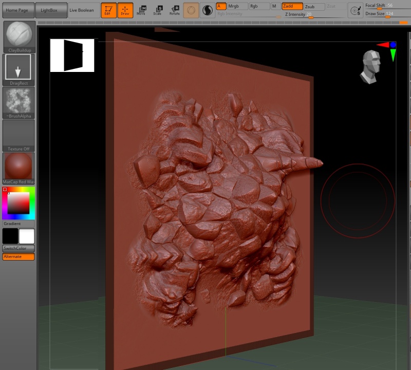
In the image below, we inserted many of the chisel brush shapes into the rockpile, and sculpted over them with the standard-type brushes with alpha images to add detail.
Now we’re ready to export the sculpted rock pile as vector displacement data for use in Terragen. Rotate the mesh so that it’s facing towards the front. You can use the “head” gizmo in the upper right, or use the “Shift” key as you rotate the mesh to help snap it into position. Be sure to turn off the Dynamic Perspective button if it is enabled.
- Rotate the mesh so that it faces the front.
- Disable the Dynamic Perspective button.
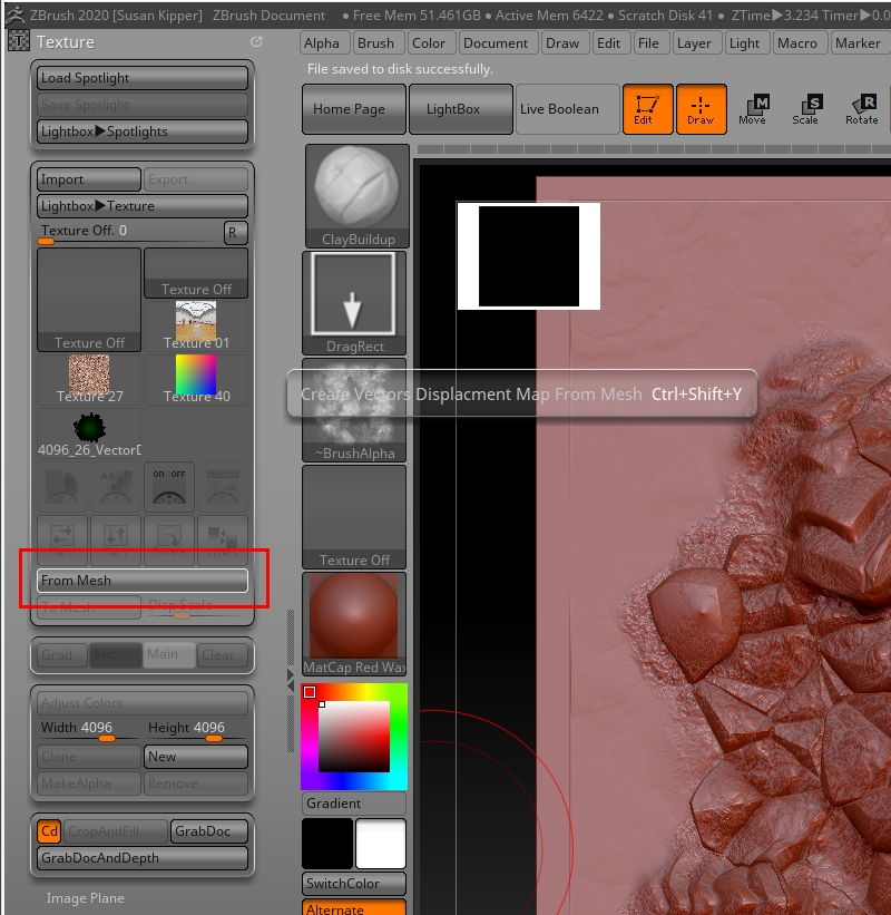
To create a vector displacement texture containing all the Zbrush modifications, click on the “From mesh” button.
- Click the “From mesh” button.
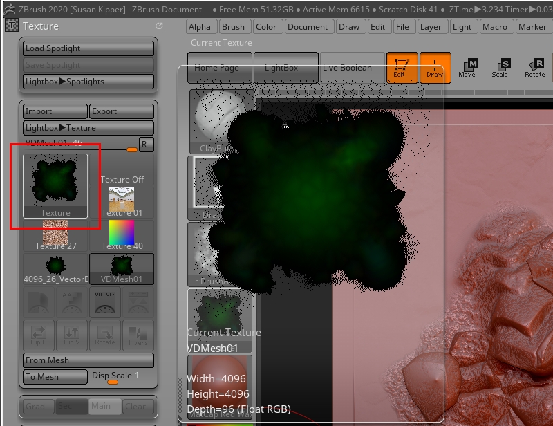
Once the texture is created, it will appear in the list. Selecting it will display a generic name, such as VDMesh01, its resolution and depth, which should be the same as when the original vector displacement image was imported.
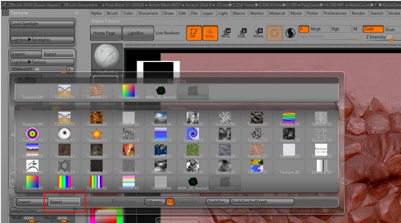
To save the texture as an EXR file, select its thumbnail to open the texture options.
- Click the texture thumbnail to open the texture options.
- Click the “Export” button.
- Save the texture as an EXR image.
And back into Terragen[edit]
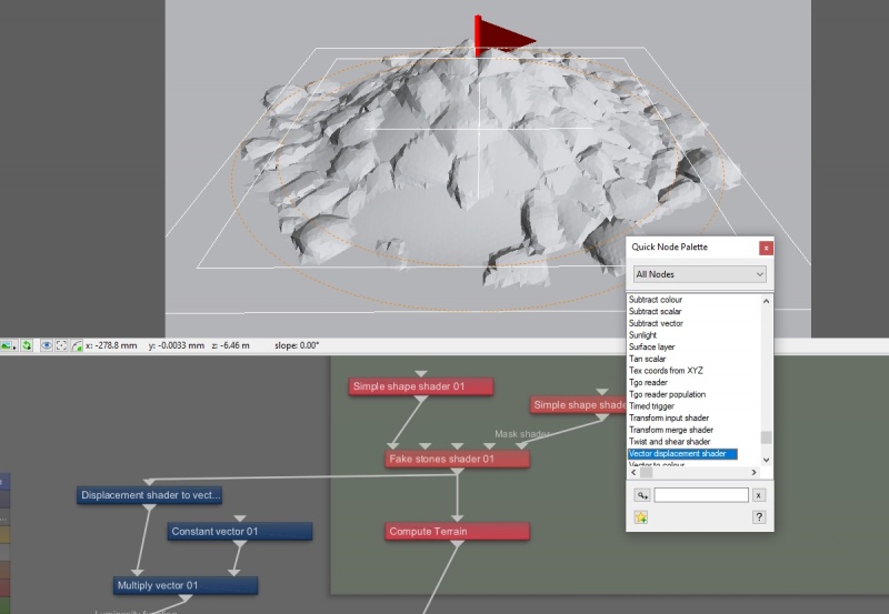
Back in the Terragen project, we’re ready to load the vector displacement data from Zbrush. Add a “Vector displacement” shader to the project via the Quick Node Palette.
- Press the tab key or “N” key on your keyboard to open the Quick Node Palette window.
- Start typing the words “Vector displacement shader”.
- When the node is highlighted in the list, press the “Enter” key.
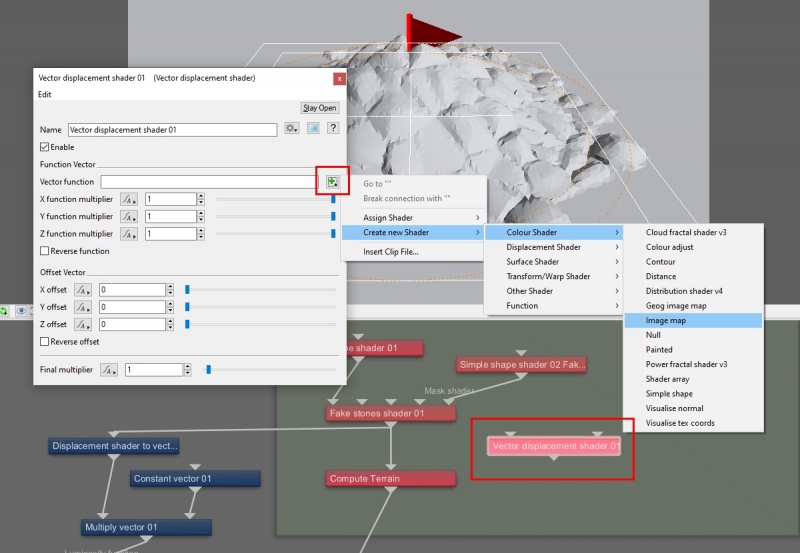
In the Vector displacement shader’s parameters, assign the EXR file exported from Zbrush, as a Vector function.
- Double-click the “Vector displacement shader” node to open its window.
- Click the green “Plus” button to the right of the Vector Function parameter.
- Select “Create new Shader > Colour Shader > Image map”.
- Navigate to the location of the saved EXR file and load it.
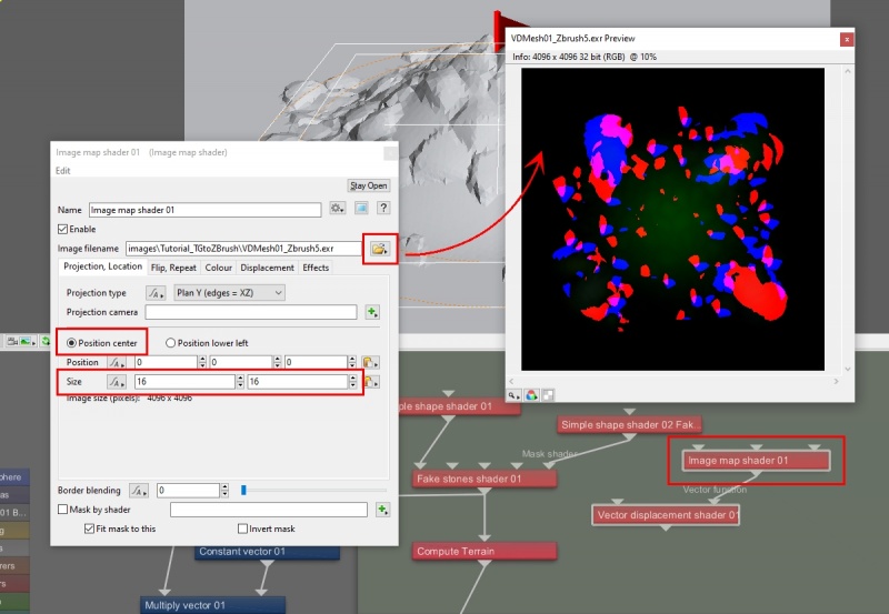
The original rendered image of the rock pile was created with the orthographic camera, and we need to set the placement and size of the new EXR file to match. Open the Image map dialog window and set the position of the image to be based on its centre, then size the image to match the orthographic camera’s “Use ortho width” setting. You can also preview the EXR image if you wish.
- Double-click the “Image map” node to open its dialog window.
- Check the "Position centre” radio button.
- Set both “Size > 16”.
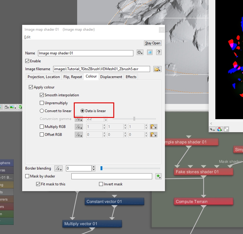
By default, the Image map shader is set to convert colour values to linear colour space, however the new EXR image is already in linear colour space, so we need to make sure that the conversion does not apply to this image.
- Click the “Colour” tab.
- Click the “Data is linear” radio button.
- Close the Image map shader dialog window.
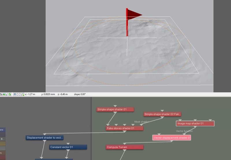
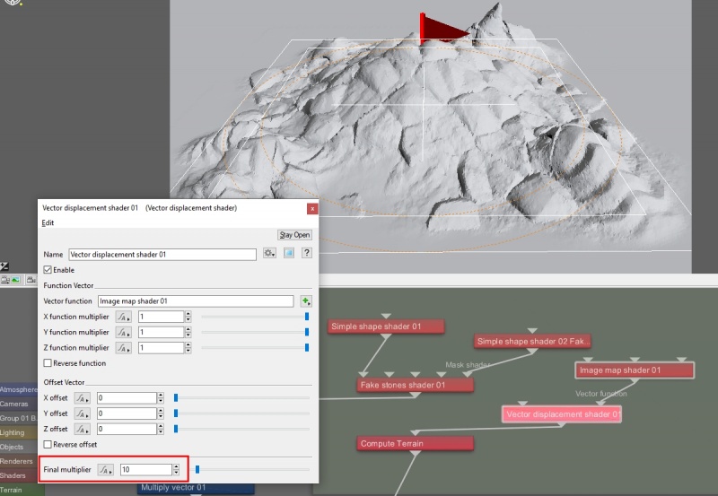
The last step is to connect the output of the Vector displacement shader to the project workflow. At first glance, the result appears not to be tall enough. This is because we had to reduce the magnitude of vector displacement in the original Terragen render, in order for it to look right in Zbrush. Now we need to return that magnitude to its correct scale.
- Drag a connection line from the “Output” of the “Vector displacement shader” node to the “Main input” of the “Compute terrain” node.
We lowered the original displacement data by a factor of 10, so now we’ll increase it by 10 using the Vector displacement shader’s “Final multiplier” parameter.
- Double click the “Vector displacement shader” node to open its dialog window.
- Set the “Final multiplier > 10”.
And there you have it! Starting with a Terragen terrain, we’ve successfully modified it in Zbrush then re-loaded it back into Terragen.
Click here to download the content files for this tutorial.
A vector is a set of three scalars, normally representing X, Y and Z coordinates. It also commonly represents rotation, where the values are pitch, heading and bank.
Literally, to change the position of something. In graphics terminology to displace a surface is to modify its geometric (3D) structure using reference data of some kind. For example, a grayscale image might be taken as input, with black areas indicating no displacement of the surface, and white indicating maximum displacement. In Terragen 2 displacement is used to create all terrain by taking heightfield or procedural data as input and using it to displace the normally flat sphere of the planet.
A heightmap or heightfield is an array of height values, usually in a grid which describe the height at specific points in a defined area. Heightfields are used to represent real-world and virtual terrain in a specific, easily converted format. Most heightfields can be represented as simple image data in grayscale, with black being minimum height and white being maximum height.
A sample refers to a value or set of values at a point in time and/or space. The defining point of a sample is that it is a chosen value out of a continuous signal. In Terragen 2 it is usually a mathematical (procedural) function that is being sampled.
A shader is a program or set of instructions used in 3D computer graphics to determine the final surface properties of an object or image. This can include arbitrarily complex descriptions of light absorption and diffusion, texture mapping, reflection and refraction, shadowing, surface displacement and post-processing effects. In Terragen 2 shaders are used to construct and modify almost every element of a scene.
A single object or device in the node network which generates or modifies data and may accept input data or create output data or both, depending on its function. Nodes usually have their own settings which control the data they create or how they modify data passing through them. Nodes are connected together in a network to perform work in a network-based user interface. In Terragen 2 nodes are connected together to describe a scene.
Literally, to change the position of something. In graphics terminology to displace a surface is to modify its geometric (3D) structure using reference data of some kind. For example, a grayscale image might be taken as input, with black areas indicating no displacement of the surface, and white indicating maximum displacement. In Terragen 2 displacement is used to create all terrain by taking heightfield or procedural data as input and using it to displace the normally flat sphere of the planet.
A parameter is an individual setting in a node parameter view which controls some aspect of the node.
In a graphical user interface (GUI) on a computer a toolbar is a row, column, or block of onscreen buttons or icons that, when clicked, activate certain functions of the program.
The bounding box is a box which surrounds (or bounds) an object or shader. This box shows the maximum extents of the item inside it. Sometimes abbreviated as "b-box".
