Compute Terrain
Compute Terrain does two things:
1) Calculate the surface normal according to a chosen "patch size".
2) Update the texture coordinates (shader coordinates) to match the current shape of the surface. It is a slightly smoother version of the terrain according to the chosen "patch size" for reasons I will explain later.
Compute Normal calculates the surface normal in the same way as Compute Terrain, but does not update the texture coordinates.
1) Surface normal
The "normal" of a surface is the vector that is perpendicular to the surface. As someone said, you can visualise a set of normals as a whole bunch of arrows pointing out of the surface. On a flat plain they would all point upwards, but on the side of a cliff the surface normal points sideways out of the cliff.
Traditionally in 3D graphics, surface normals would be used for lighting calculations. But with the advent of displacement shaders we also need some direction in which to displace the surface, and usually this is along the surface normal (although not always).
Displacement can happen in any direction in TG2, but most shaders default to displacing along the surface normal. This is usually what we want so that rocks can jut out the side of steep cliffs instead of distorting the side of the cliff up and down. If there is no Compute Terrain or Compute Normal, the surface normal is simply the local "up" vector, which is the vector that points away from the centre of the planet. (For other objects the situation is different, but Compute Terrain and Compute Normal are only recommended for use on a planet.)
"Patch size" affects how rapidly the surface normal changes with respect to position on the surface. It is important to understand this if you have very large displacements occurring after the surface normal has been calculated. Imagine, for example, that you have a displacement shader that creates 100 metre spikes and you apply it after the Compute Terrain or Compute Normal. If the underlying terrain is fairly rough and the Compute Terrain's "patch size" is only 1 metre, the surface normal will change direction very rapidly. The spikes will overlap in some places and spread out far to much in others. In this case the solution would be to increase the patch size, perhaps to 100 metres, so that the surface normal changes more gradually.
The surface normal is also used for other purposes such as slope constraints in the Surface Layer and in the Distribution Shader. If you use the Surface Layer to apply displacement or use the Distribution Shader to control displacement, then the surface normal is important if you use slope constraints.
"Final normal":
However, if you use slope constraints to control only the colour or other non-displacement attributes of a surface, usually you don't need to worry about the surface normal. This is automatically calculated from the micropolygons after all displacement has been applied, and this is called the "final normal". This gives you the highest level of detail. In some shaders you have the option of changing which type of normal you want to use when applying effects based on slope or similar, and this is sometimes useful if you want the constraints to be applied identically to both displacement and colour.
You don't need to worry about surface normals for lighting calculations in Terragen 2. All shaders in TG2 currently use the "final normal" for lighting calculations.
2) Texture coordinates
There are many shaders in TG2 which apply both displacement and colour, and it's important that the colour and displacement align as closely as possible. All colour and non-displacement shading effects happen after all the displacement from all shaders has occurred. This can lead to problems with shaders that are part way through the displacement chain, because they operate on a surface which does not know its final position after the remaining displacements have been calculated. That is OK if they only perform displacement, but if they apply colour that needs to align with the displacement there will be a mismatch.
To solve this problem, most shaders in TG2 use texture coordinates and feed those into their noise functions for calculating both colour and displacement. Initially the texture coordinates at any point on the terrain are simply the 3D coordinates of that part of the terrain prior to any displacement, or in other words the flat part of the planet that terrain was displaced from. Unfortunately this makes it impossible to texture the sides of cliffs without stretching the texture (and also causes other problems because so many shaders need to use the texture coordinates), so at some stage in the shader chain we need to copy the texture coordinates from the displaced terrain coordinates. Compute Terrain does this for us as well as computing the normal. You can also use "Tex coords from XYZ" (in Shaders -> Other) to copy these coordinates without recomputing the normal.
It is important that the texture coordinates are updated before any colour or non-displacement shading occurs, otherwise the colour and non-displacement will not match the displacement correctly.
"Smoothed texture coordinates"
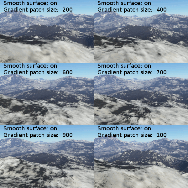
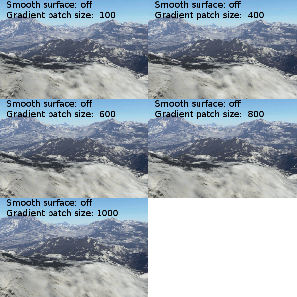
The Compute Terrain node performs both of the above functions (surface normal and texture coordinates). However, when it calculates the texture coordinates it actually generates a slightly modified version of the coordinates which are later used for special effects in the Surface Layer, and these are the "smoothed texture coordinates".
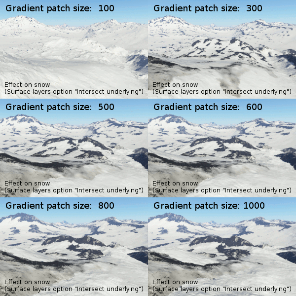
The smoothed texture coordinates serve as a smoother version of the terrain that can be utilised by the "Smooth effect" in the Surface Layer shader. These smoothed texture coordinates are also essential to the correct functioning of the "Intersect Underlying" feature in the Surface Layer. This is broken in the current public release (build 1.8.76.0) but has been fixed and improved for the next update.
The scale over which the smoothing effect operates is controlled by the "patch size" in the Compute Terrain, and this therefore affects the results of the "Intersect Underlying" feature. I intend to provide some documentation on this upcoming feature when we release the update.
Motivation for the Compute Terrain node
We decided that it would be useful to combine both surface normal and texture coordinates into a single node so that it is easier to separate the concepts of "terrain" and "surface shaders" and delimit them with a single node. Any large scale displacements that you apply should happen before the surface normal is computed, and it also helps if you avoid doing any colouration prior to this. So we wrapped everything up into a single Compute Terrain node. Any shaders that apply colour should come after the Compute Terrain so that displacement and colour can be aligned properly and so that slope and altitude constraints work properly. It also ensures that "smoothed texture coordinates" are available to any Surface Layer that need to use them for its smoothing effect or Intersect Underlying effect.
Compute Terrain also serves another purpose: it indicates to the user interface the point at which to separate shaders into the separate Terrain node list and Shaders node list. This helps to encourage the use of large scale displacements (terrains) before the Compute Terrain and all other shaders after it, via the popup menus. This is one aspect of the interface that I hope we can improve upon in future, as it's still very clumsy and not at all clear why it works this way.
When to use additional Compute Normal or Compute Terrain nodes
When you perform large scale displacements prior to the Compute Terrain, sometimes you need to limit them according to slope or altitude. If you need them to know about altitude, use a "Tex Coords From XYZ" node because this is very fast to compute. If your displacements need to know about slope, for example if you use a Distribution Shader to affect displacement, use a Compute Normal. However, beware that Compute Normal and Compute Terrain slow down computation of their inputs, and the slow-down is compounded each time they are used. The slowdown only applies to the input shader network, so if they are high in the shader chain the slowdown can be minimised. It multiplies the time needed to compute the input displacement by a factor of approximately 3.
Example Movies
A shader is a program or set of instructions used in 3D computer graphics to determine the final surface properties of an object or image. This can include arbitrarily complex descriptions of light absorption and diffusion, texture mapping, reflection and refraction, shadowing, surface displacement and post-processing effects. In Terragen 2 shaders are used to construct and modify almost every element of a scene.
A vector is a set of three scalars, normally representing X, Y and Z coordinates. It also commonly represents rotation, where the values are pitch, heading and bank.
Literally, to change the position of something. In graphics terminology to displace a surface is to modify its geometric (3D) structure using reference data of some kind. For example, a grayscale image might be taken as input, with black areas indicating no displacement of the surface, and white indicating maximum displacement. In Terragen 2 displacement is used to create all terrain by taking heightfield or procedural data as input and using it to displace the normally flat sphere of the planet.
Literally, to change the position of something. In graphics terminology to displace a surface is to modify its geometric (3D) structure using reference data of some kind. For example, a grayscale image might be taken as input, with black areas indicating no displacement of the surface, and white indicating maximum displacement. In Terragen 2 displacement is used to create all terrain by taking heightfield or procedural data as input and using it to displace the normally flat sphere of the planet.
A single object or device in the node network which generates or modifies data and may accept input data or create output data or both, depending on its function. Nodes usually have their own settings which control the data they create or how they modify data passing through them. Nodes are connected together in a network to perform work in a network-based user interface. In Terragen 2 nodes are connected together to describe a scene.
The Node List is a part of the Terragen interface that shows a list of nodes along the left side of the application window. The Node List generally shows only those nodes that are relevant to the current Layout (e.g. Terrain, Atmosphere). It sometimes includes buttons or other controls that are specific to a particular Layout as well. The Node List is hierarchical and each level is collapsible.


