Power Fractal Shader v3
Contents
Overview[edit]
The Power Fractal Shader is one of the most important and fundamental shaders used in Terragen. Based on a choice of fractal formulas, it provides the user with the ability to create and control the distribution and displacement of many functions in any Terragen project. The fractal detail provided by this shader is user-defined and adaptable to any scale required, ranging between the order of magnitude of a tiny grain of sand, up to planetary structures.
Usually, the Power Fractal Shader is sourcing information to other shaders, such as a surface shader or cloud shader, which then interpret the fractal information provided, relative to the functions these other shaders perform.
Fractals can be used for displacement or for colour, or for both displacement and colour. When we refer to the amplitude of a feature, this is related to the "displacement amplitude" when used for displacement or the "colour contrast" when used for colour. The colour generated by a shader is often interpreted in other ways when connected to other shaders. Examples are the density of a cloud layer or the fractal breakup applied to another surface layer.
Scale is measured in texture space, which is not the same as the "tallness" of a feature. For example, you can have a feature scale of 100 km but its features only 10 metres tall.
The default scene contains a Power Fractal Shader which has been renamed "Base Colors". This shader provides color to the planet surface. To be precise, it provides a fractal distribution of colors, ranging from grey to black, at a certain fractal detail, contrast and color roughness. Under its Displacement Tab, the “Apply displacement” checkbox has been disabled so as not to provide additional 3D structure to the planet surface.
Settings
- Name: This setting allows you to apply a descriptive name to the node, which can be helpful when using multiple Power fractal shader nodes in a project.
- Enable: When checked, the node is active and the settings below will affect the surface. When unchecked, the node is ignored.
- Seed: This setting controls the noise pattern generated. Each seed value generates a slightly different pattern. You can either set the value manually or use the Random Seed button at right to generate a random value.
- Random seed: Clicking this button will randomly choose a new value for the “Seed” setting.
- Mask by shader: When checked, the Power fractal shader is masked by the shader or function nodes assigned to this setting. Whiter parts of the masking shader show more of the image map. Shades of grey control the opacity of the image map.
- Fit mask to this: When checked, the masking shader or function nodes are remapped to fit into the area of the image map shader. When unchecked, the masking shader determines the area to which the mask is applied.
- Invert mask: When checked, the shader or function nodes assigned to the Mask by shader input are inverted. For example, light parts become dark and vice versa.
Scale Tab[edit]
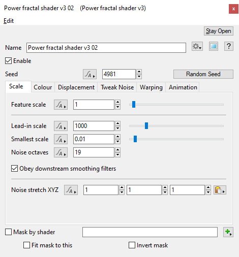
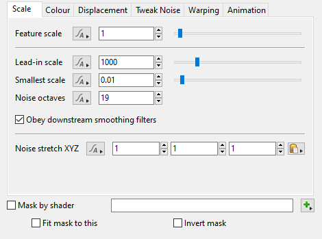
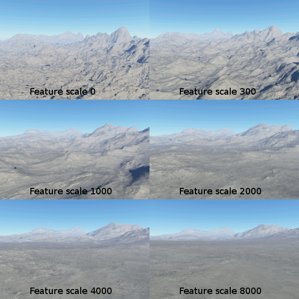
- Feature scale: The dominant features in the fractal pattern occur at the "feature scale", therefore any positive value may be used. Features that are smaller than the feature scale have a reduced amplitude, that is, the amplitude continues to diminish as the scale gets smaller, at a rate that depends on the roughness parameters.
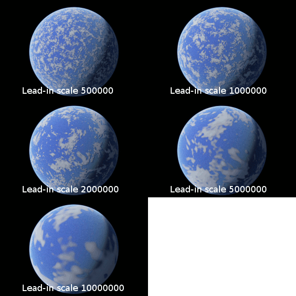
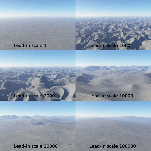
- Lead-in scale: This setting should always be the largest feature that is visible in the texture. Any positive value may be used. With clouds, for example, the lead-in scale allows you to create variations that occur over large areas of the sky, even if you want more prominent features at a smaller scale.
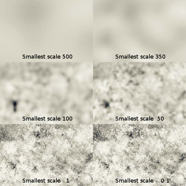
- Smallest scale: This setting may be any positive value, and sets the fractal pattern’s limit for producing detail, so that the shader does not calculate detail to an infinite level. The fractal does not create detail below this scale. If this is the only fractal in your surface or texture, then it will be smooth below this scale.
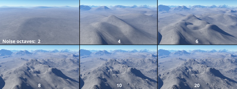
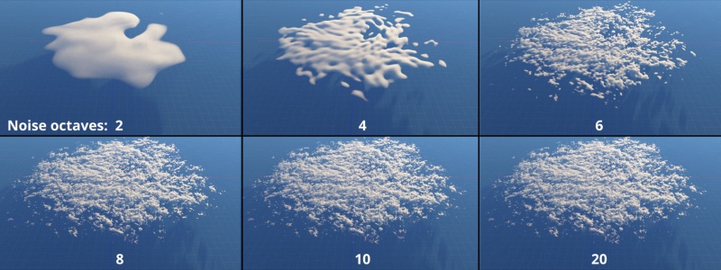
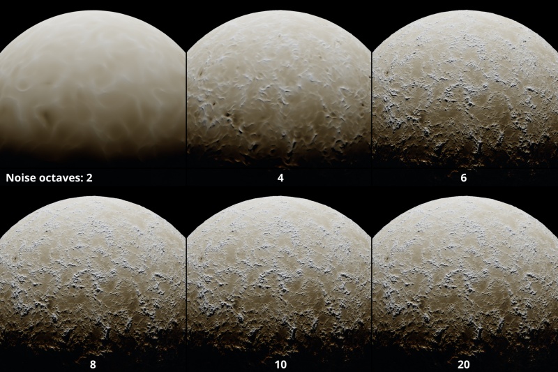
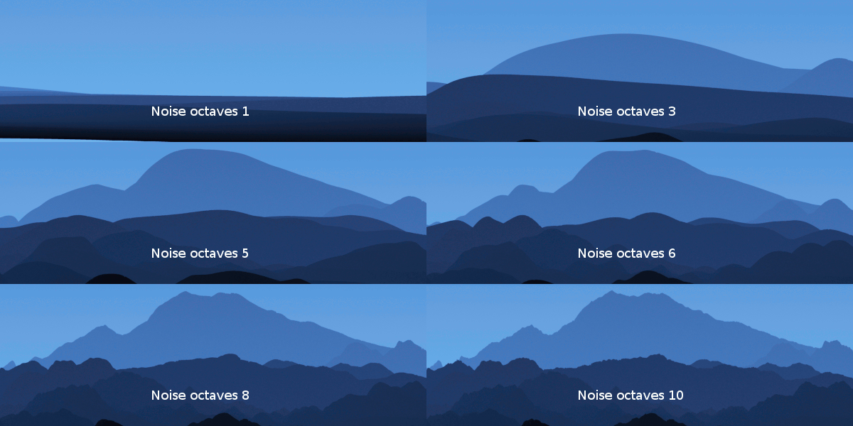
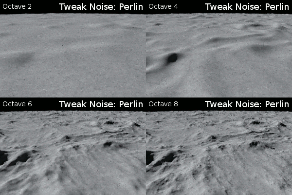
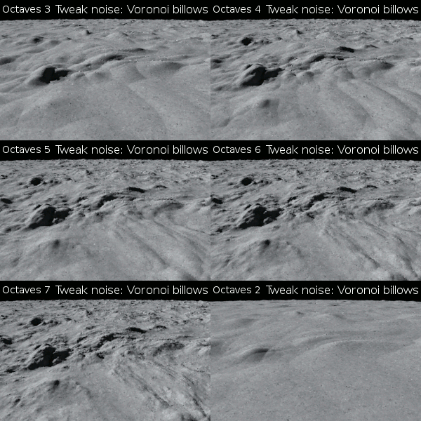
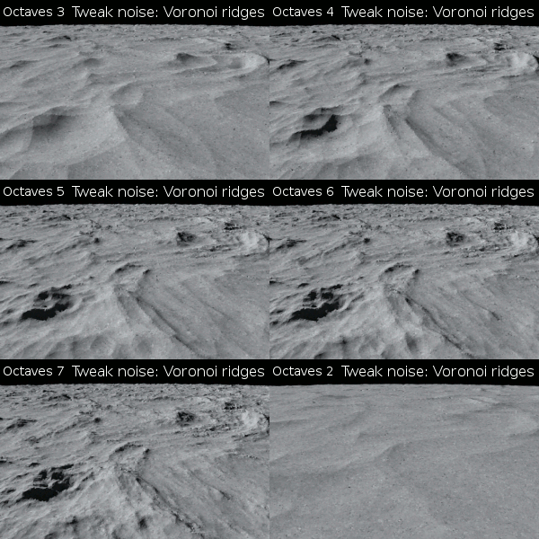
- Noise octaves: This setting controls the number of layers which are combined to make up the noise pattern. The noise in each additional layer is twice the frequency of the previous layer. This has the effect of adding finer detail to the noise pattern.
- Obey downstream smoothing filters: This setting allows the shader to take into consideration the Smoothing scale setting value of any Smoothing filter shaders located downstream from its position in the node network. The Smoothing filter forces the Power Fractal shader not to generate features smaller than its Smooth scale value thereby smoothing the output of the Power Fractal shader..
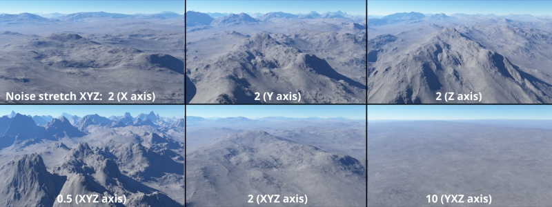
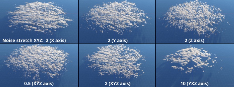
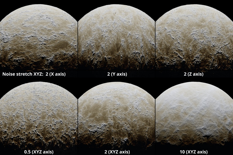
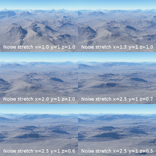
- Noise stretch XYZ: This setting stretches, or scales, the noise pattern along the XYZ axis.
Colour Tab[edit]
The settings on this tab allow you to tweak the color information generated by the fractal, which in turn impacts the functions or nodes reading the information from this shader.
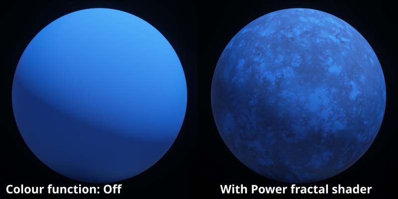
For example, a Power fractal shader with a colour range from black to white might be assigned to the Colour function parameter of a Surface layer in order to create variations of the colour defined by its Apply colour setting.
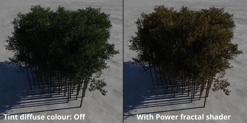
Or, a Power fractal shader might be used to tint a tree population, changing their folliage from green to autumnal colours.
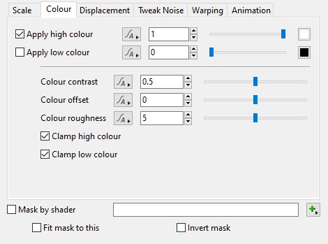
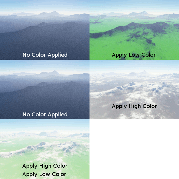
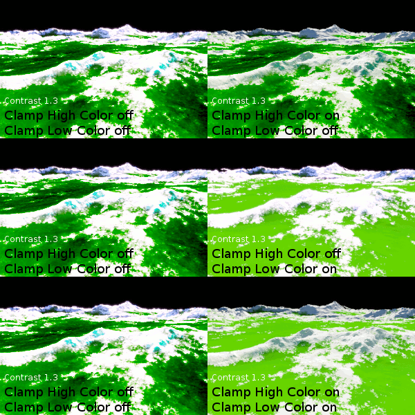
- Apply high colour: When checked, the colour value to the right determines the high end of the power fractal’s colour range. The Power fractal shader generates a range of colours between this setting and the Apply low colour setting. When unchecked, the colour values defined by other shaders upstream from this shader are passed through.
- Apply low colour: When checked, the colour value to the right determines the low end of the power fractal’s colour range. When unchecked, the colour values defined by other shaders upstream from this shader are passed through.
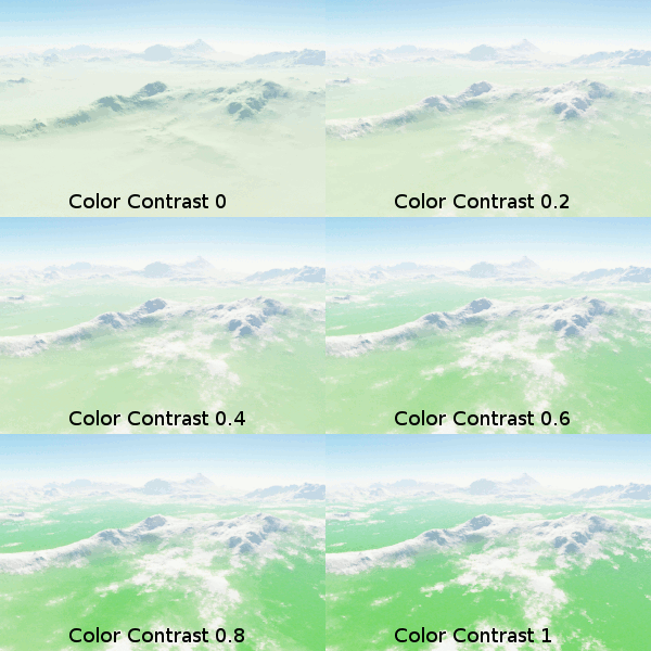
- Colour contrast: This setting adjusts the contrast between the colors generated by the fractal.
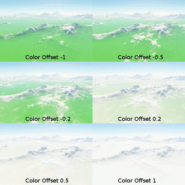
- Colour offset: This setting is used to adjust the bias between the Apply high colour and Apply low colour values. At the default value of zero the two colours are considered “in balance”. Lowering the value below 0 strengthens the effect of the Apply low colour, while increasing the value above 0 strengthens the effect of the Apply high colour.
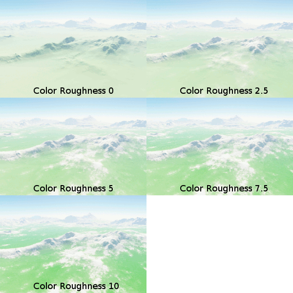
- Colour roughness: This setting controls the transitions between the colour values. The lower the value the smoother the transition, and the higher the value the sharper and more abrupt the transition.
- Clamp high colour: The Power Fractal shader generates values above white or 1.0. When checked, this setting stops the fractal from generating values greater than 1.0.
- Clamp low colour: The Power Fractal shader generates values below black or 0.0. When checked, this setting stops the fractal from generating values below 0.0.
Displacement Tab[edit]
Displacements are one of the two main functions of the Power Fractal Shader. When displacement is enabled in this shader, the color information generated by the fractal is interpreted as elevations; where the high color equals maximum elevation, and the low color is the minimum elevation. The elevation information is independent of the color chosen in the Colour tab of the Power Fractal Shader. In fact, colors can be completely disabled in the Power Fractal Shader and displacement information is still generated for use by other shaders and functions.
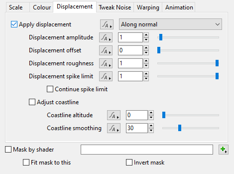
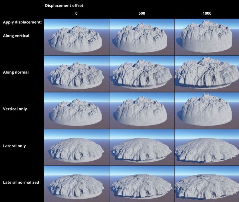
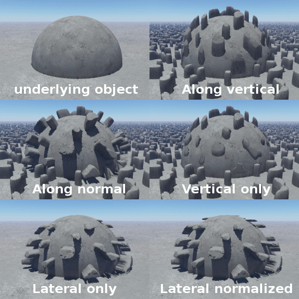
- Apply displacement: When checked, the shader will generate displacement. This popup menu contains five options which allow you to choose the direction that displacement is applied in. Options in the popup list that have "(requires computed normal)" require that there be a Compute Terrain or Compute Normal connected somewhere above the node in the network to work properly.
Along vertical: Displacement happens along the original normals of the underlying object (i.e. the planet or a model) prior to any displacement having been applied.
Along normal: Displacement happens along the current surface normal.
Vertical only (requires computed normal): Displacement only happens along the normal of the underlying object (i.e. the planet or a model). The displacement is scaled by the difference between the object normal and the surface normal. Displacement is reduced as the angle between the normals approaches 90°.
Lateral only (requires computed normal): Displacement only occurs in the lateral plane, or in other words perpendicular to the normal of the underlying object.
Lateral normalized (requires computed normal): This is the same as Lateral only but the normal is normalised, that is scaled so it has a length of 1.
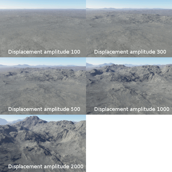
- Displacement amplitude: This value defines the full range of amplitude in metres a surface can be displaced. Half of this value displaces in the positive direction and half in the negative direction. Where the noise pattern is at its highest value (white) the surface is displaced half of the value along its positive vector, and where the noise pattern is at its lowest value (black) the surface is displaced half the value along its negative vector. For example, with a Displacement amplitude value of 4, a "Y up" flat surface will displace upwards 2 metres where the noise pattern is white, and downwards 2 meteres where the noise pattern is black.
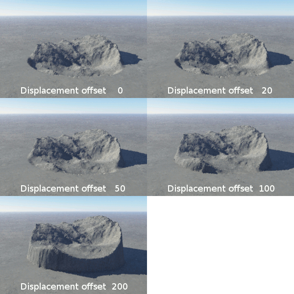
- Displacement offset: This value is added to the displacement values, offsetting the displacement by a set amount along the displacement direction. Positive values push the displacement out so it looks almost as if it was sitting on a plinth. Negative values will sink the displacement back into the surface. It doesn't reverse the displacement, it's more like creating a hole in the surface and then applying the displacement to the bottom of the hole.
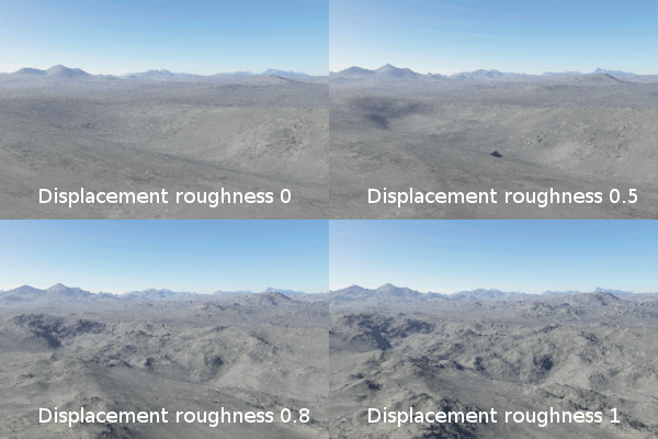
- Displacement roughness: This setting controls roughness of the displacements. Values less than 1 reduce the roughness of the displacement.
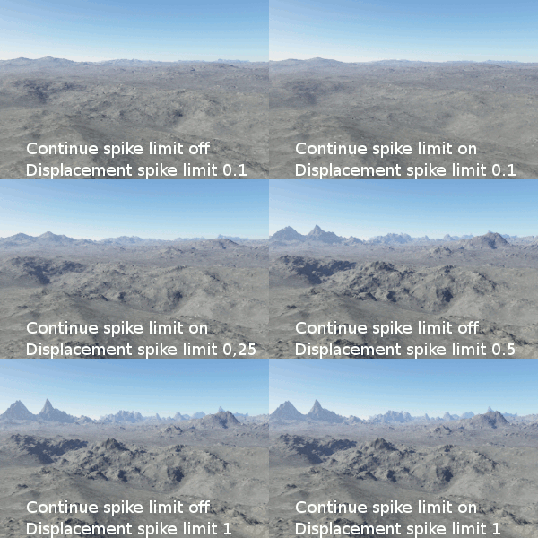
- Displacement spike limit: This setting prevents individual noise elements from becoming too high in amplitude. It works similarly to a gradient limit, putting a damper on how steep the noise features can get. Without damping, the fractal can end up with very steep and spikey features caused by high roughness, high displacement or high variation settings. While you might want to use these high roughness values to drive steeper and rougher terrain at small scales, you still need a way to stop the roughness getting out of hand in some places due to amplitude variations.
- Continue spike limit: When unchecked, the Displacement spike limit only limits the amplitude of each octave independently. When checked, whenever some noise element is affected by spike limit it remembers the reduction in amplitude and applies that reduction to further (smaller scaller) octaves that overlap the same region. This allows roughness and noise variation to continue to have effects on smaller scales even on parts of the fractal where the amplitude is being limited, and in most cases results in a smoother, yet more varied, appearance of steep surfaces where larger scale octaves were producing excessive amplitude.
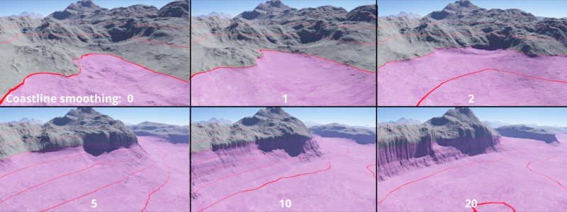
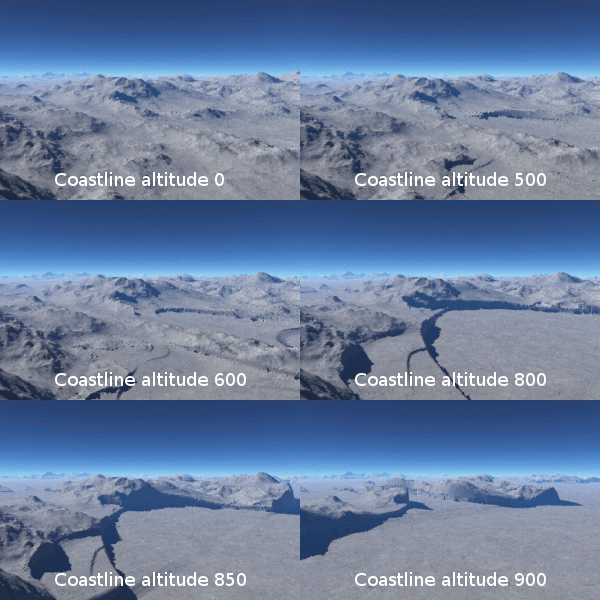
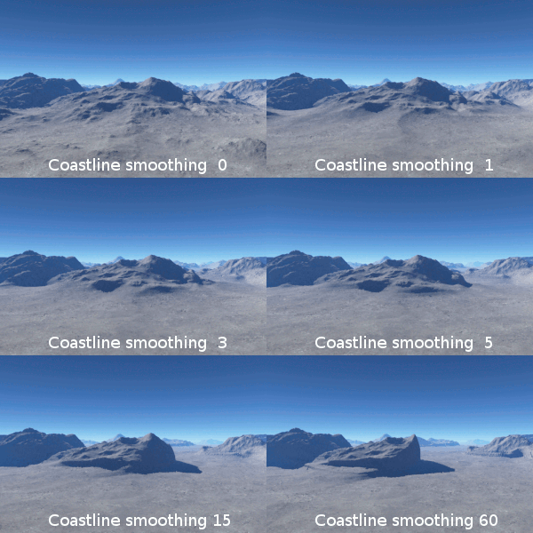
- Adjust coastline: When checked, displacements will be smoothed by the Coastline altitude and Coastline smoothing settings below.
- Coastline altitude: This setting controls the altitude where the smoothing effect begins.
- Coastline smoothing: This setting determines the amount of smoothing. A value of 0 results in no smoothing.
Tweak Noise Tab[edit]
This tab has settings which let you control the "noise" pattern used for the fractal. In relation to fractals, "noise" is a pseudo-random, space-filling texture primitive. The actual look of the generated texture changes by choosing a different seed from which the noise functions begins to calculate. Think of "noise" as a way to add pseudo-random variation to a fractal, which by definition is self-similar over all magnitudes. So "noise" combined with the structures pre-defined by a fractal produces a multi-dimensional density function, which Terragen uses for things like procedural terrain generation and clouds, as well as masking, displacements, colouring of structures, etc. The most fundamental characteristics of the final density function generated by a Power Fractal are determined by the flavour of noise chosen in this tab.
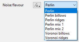
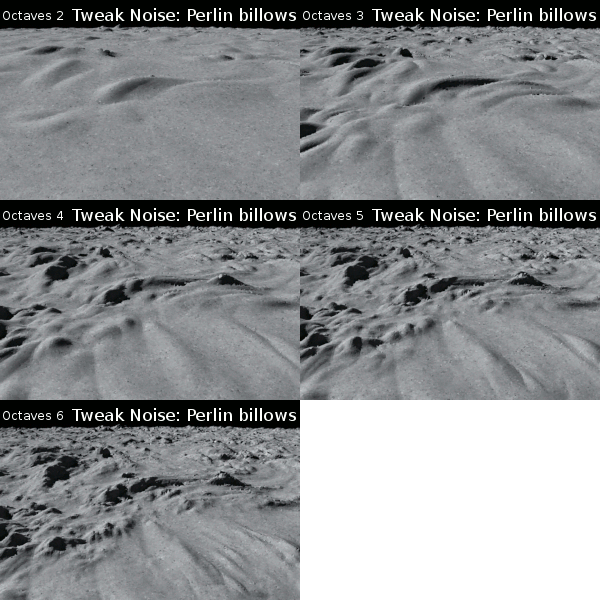
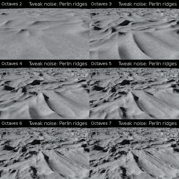
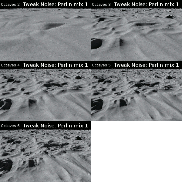
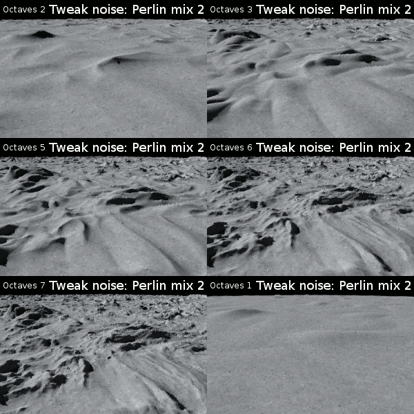
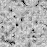
- Noise Flavor: This popup has seven options which support the following different flavours of noise:
| |||
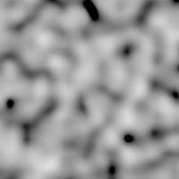
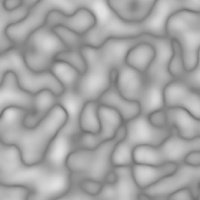
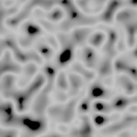
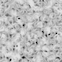
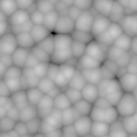
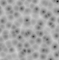
These example images use a single octave of noise, aside from the two Perlin mix flavours which use two octaves. This helps to show the underlying pattern more clearly. The "billows" and "ridges" patterns are variations of their basic flavour. "Billows" patterns are a bit like a whole lot of bubbles. Generally speaking they have smooth rounded tops dropping down to quite sharp joins between different blocks of the pattern. In fact the voronoi billows pattern looks a lot like bubbles. You might also think of "billows" as rounded hills separated by steep sharp gullies. The "ridge" patterns are the opposite of the "billows" patterns. It's the same overall pattern but inverted. This means it has narrow sharp ridges which drop down to rounded bottoms. The two "Perlin mix" flavours are a combination of the other Perlin flavours.
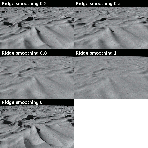
- Ridge smoothing: This setting controls smoothing of the ridges generated by the fractal. A value of 0 means ridges are at their sharpest. Higher values make ridges smoother and smoother. This parameter is only available for some noise flavours.
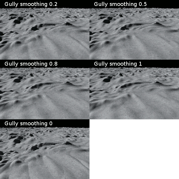
- Gully smoothing: This setting controls the smoothing of the low gullies created in "billows" patterns. A value of 0 means gullies are at their steepest. Higher values makes the gullies less steep and have an effect rather like they were being filled in. This parameter is only available for some noise flavours.
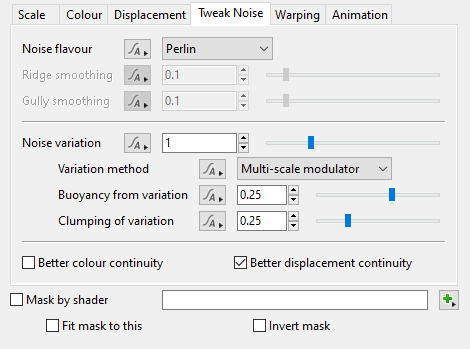
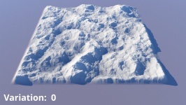
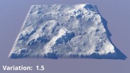
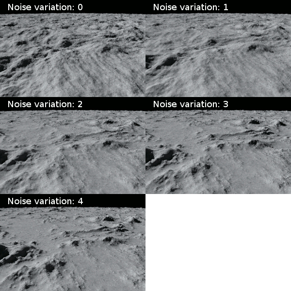
- Noise variation: Sets the overall noise variation. At value 0, the noise generated shows an even distribution of small and large texture components. At higher values, the noise varies more unevenly, creating a noise texture with an uneven amount of large and small features.
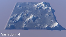
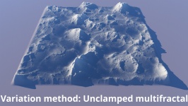
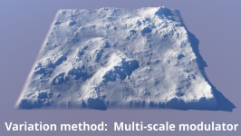
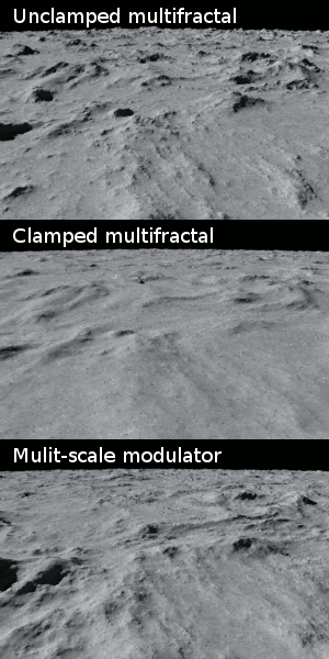
- Variation method: This popup menu provides three options for applying the "Variation" to the fractal noise pattern.
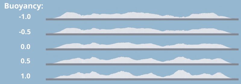
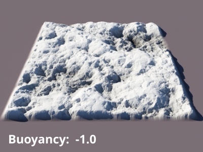
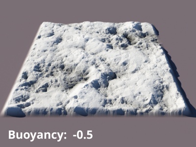
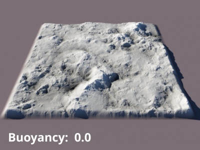
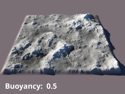
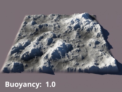
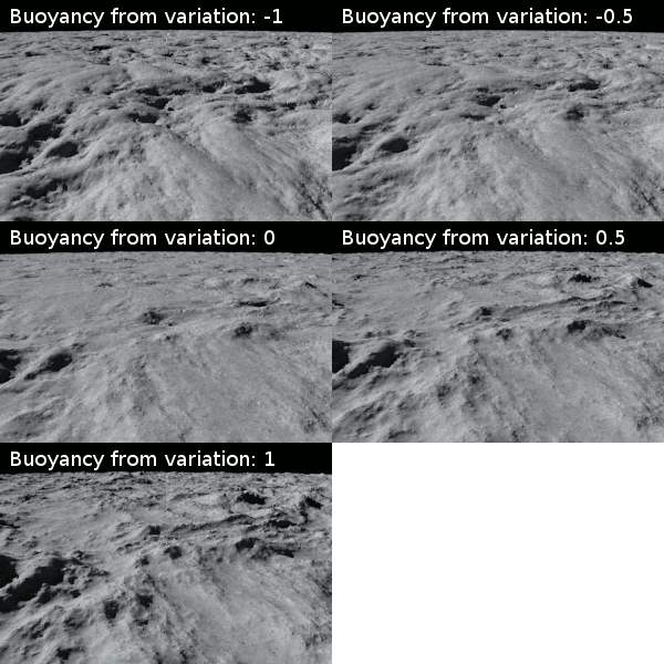
- Buoyancy from variation: When the "Variation method" is set to Multi-scale modulator, this setting allows the rough peaks of the terrain to rise in height and the valley areas to lower and become smoother. Note, this setting has no effect on Clamped and Unclamped multifractal variation methods.
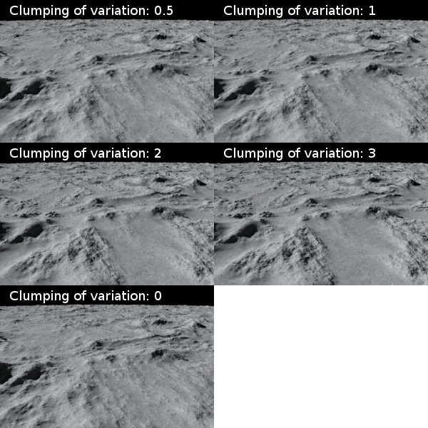
- Clumping of variation: This setting adjusts the distribution of variation changes. Higher values result in a clumping effect. For example, when the fractal is used for creating a procedural terrain, a high clumping value would account for distinct areas of plains and mountains, especially when combined with a higher than default value for Noise variation.
- Better colour continuity: When enabled, the shader uses more precise math to remove C1 discontinuities in the chosen Variation method option. A C1 discontinuity is a change in the tangent of a curve, in other words, a kink in the curve. The shader changes how the smoothing of ridges and gullies is performed in Perlin Ridges, Perlin Billows and Perlin Mix noise flavours to give smoother results.
- Better displacement continuity: When enabled, the shader uses more precise math to remove C1 discontinuities in the chosen Variation method option. A C1 discontinuity is a change in the tangent of a curve, in other words, a kink in the curve. The shader changes how the smoothing of ridges and gullies is performed in Perlin Ridges, Perlin Billows and Perlin Mix noise flavours to give smoother results.
Warping Tab[edit]
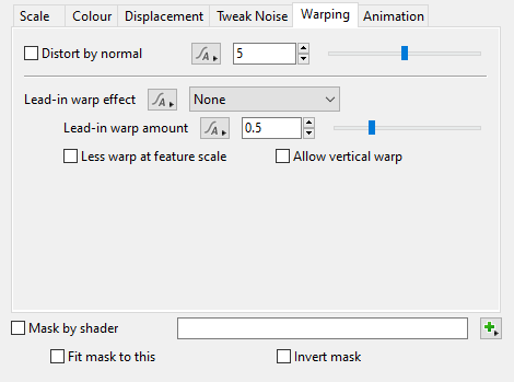
The settings on this tab, allow you to warp, or distort, the noise pattern generated by the shader’s previous tabs and settings.
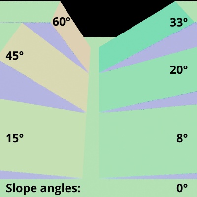
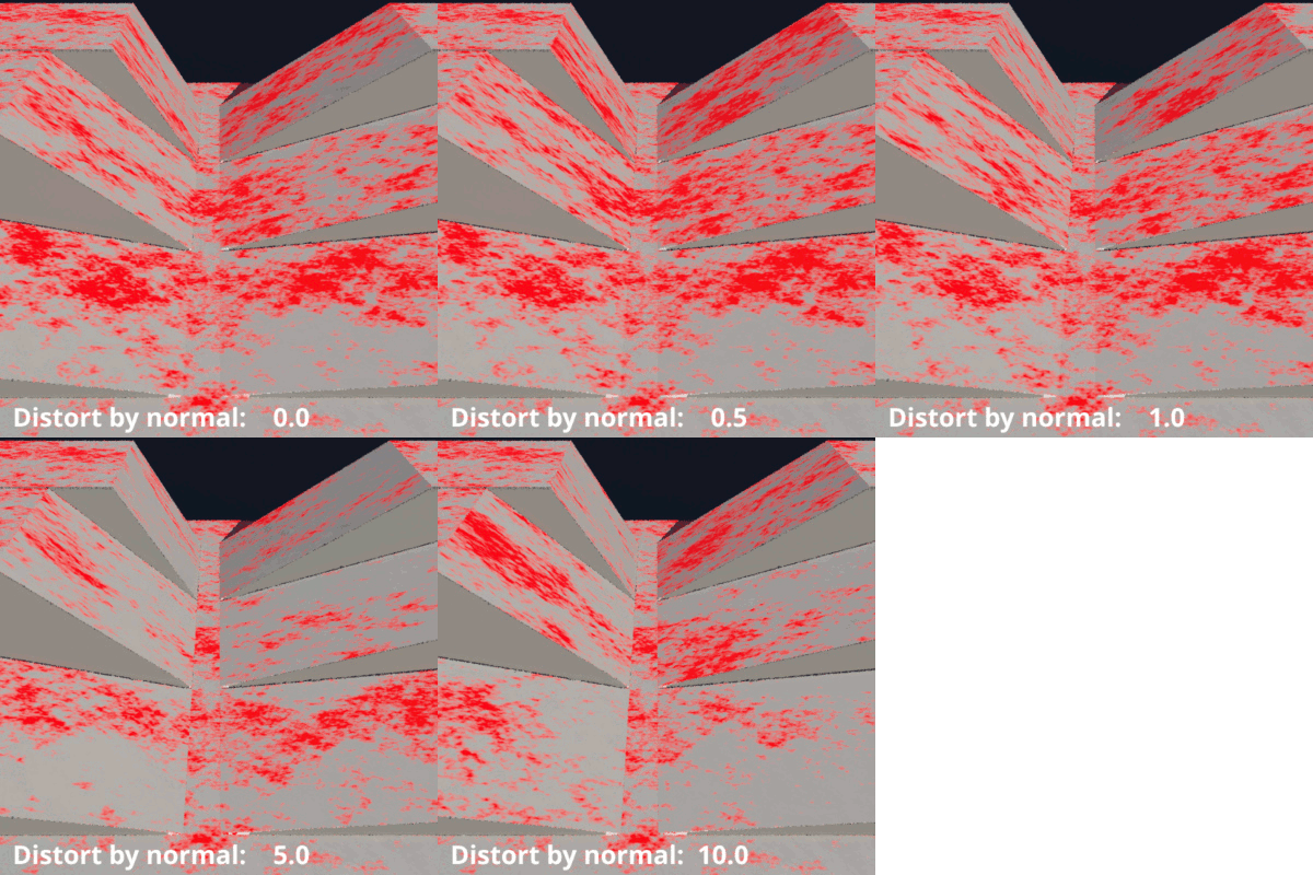
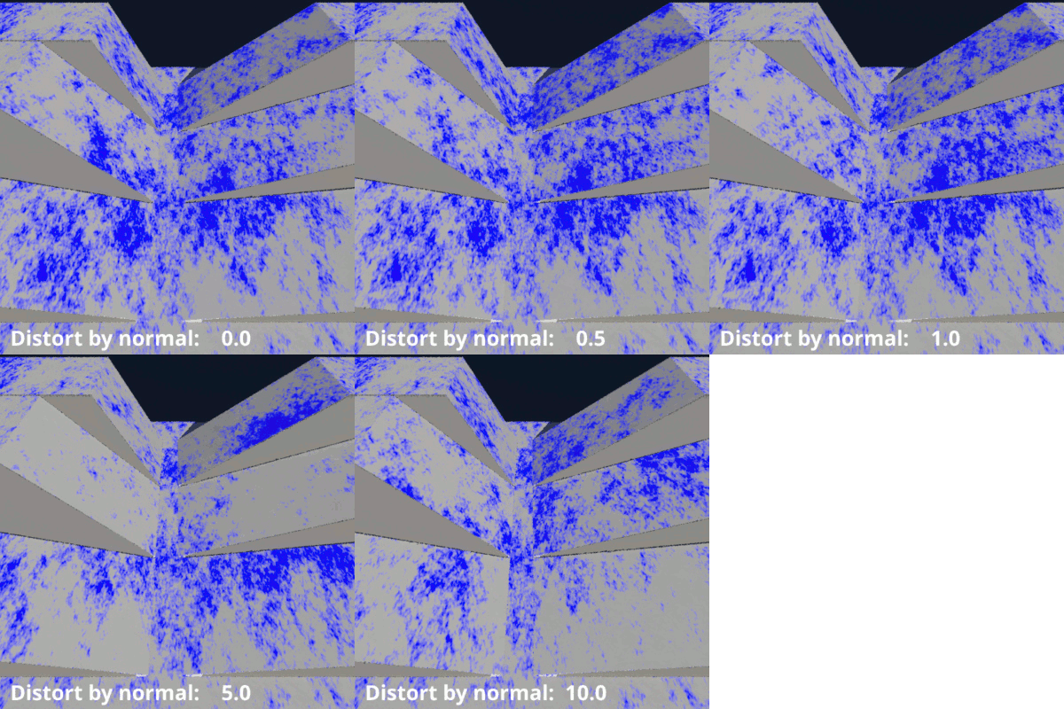
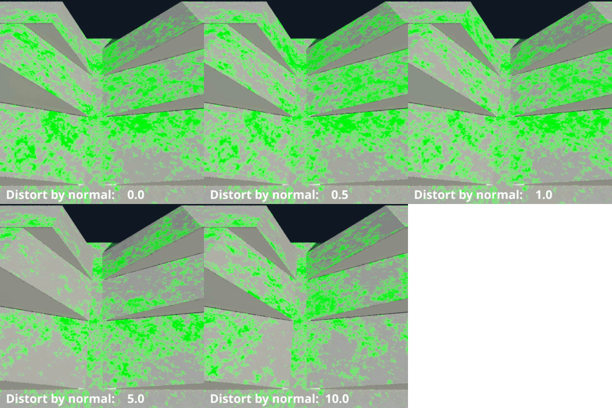
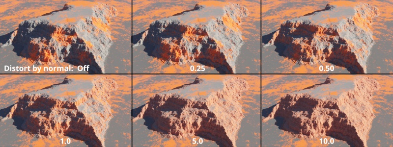
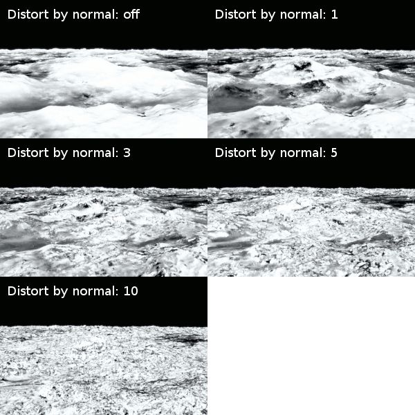
- Distort by normal: This setting controls how much distortion to apply to the fractal colour, based on the value of its surface normal. A normal value of 0 results in no distortion. This setting has no effect on the fractal’s displacement. In the examples below, as a slope increases from 0 to 90 degrees its normal value increases from 0 to 1.0. As the Distort by normal value increases, the greater the distortion to the fractal colours where the surface normal value is higher. Note that where the slope angle, or normal, is 0 there is no distortion to the fractal colour no matter how high the value of the Distort by normal setting.
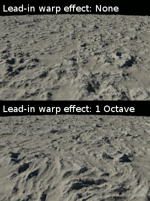
- Lead-in warp effect: This popup menu has two options and allows the internal noise pattern to either be warped or left unwarped.
None: Does not warp the internal noise pattern.
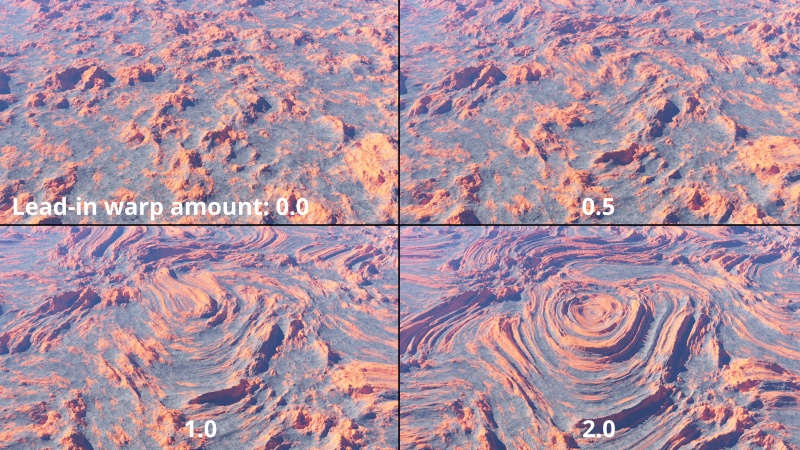
1 Octave Perlin Warp: Warps the noise pattern with a single octave noise pattern of the same scale as defined in the Lead-in scale setting under the Scale tab. This introduces large swirl-like patterns to your noise pattern. It affects both the fractal pattern’s colour and displacement.
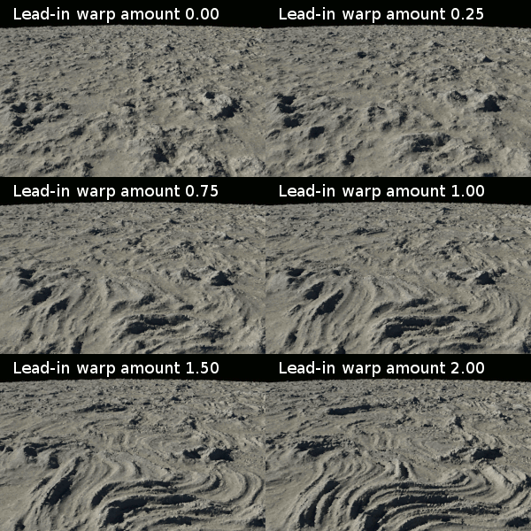
- Lead-in warp amount: Controls the amount of warp. A value of 0 is the same as setting the Lead-in warp effect to "None". Higher values create more pronounced swirl-like patterns.
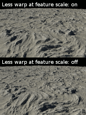
- Less warp at feature scale: When checked, applies less warping to features of the noise pattern the same scale as defined by the Feature scale setting under the Scale tab. In other words, smaller scale features are less affected by the warping.
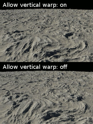
- Allow vertical warp: When checked, allows for the internal noise pattern to be warped vertically, in the “Y” axis, as well as the “X” and “Z” axis.
Animation Tab[edit]
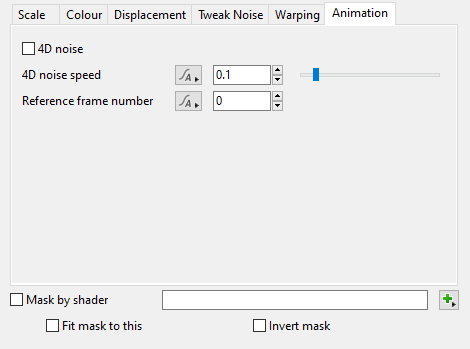
- 4D noise: When checked, 4D noise is enabled. 4D noise is always different from 3D noise, so expect deformations to change when this setting is enabled.
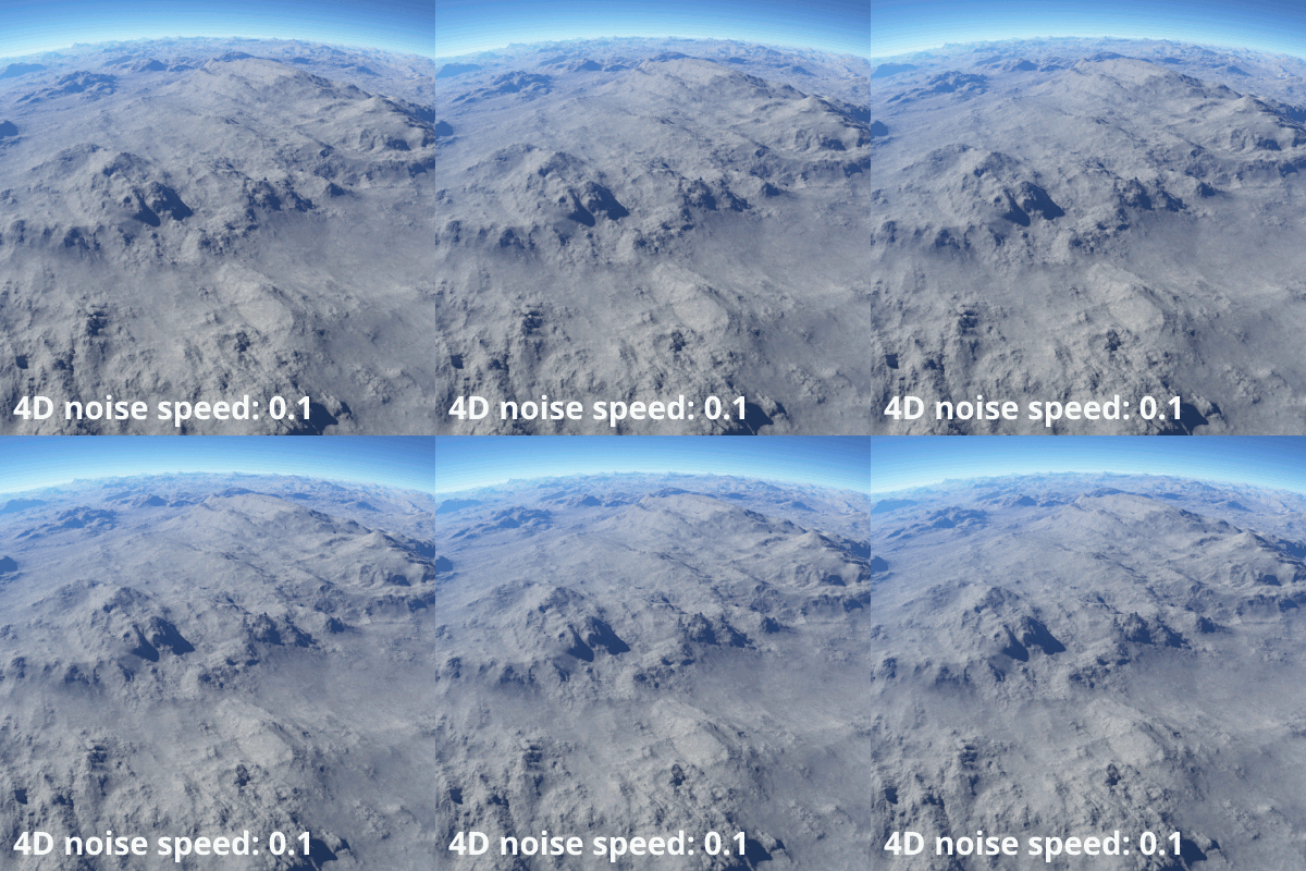
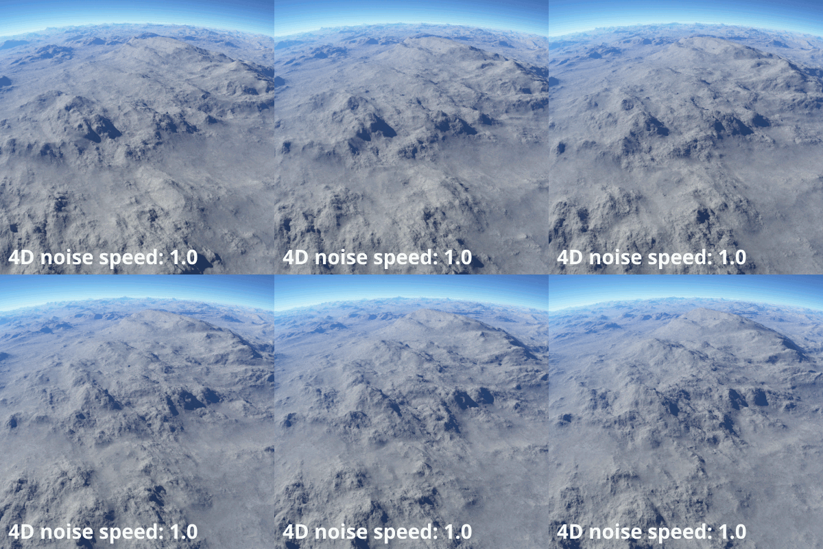
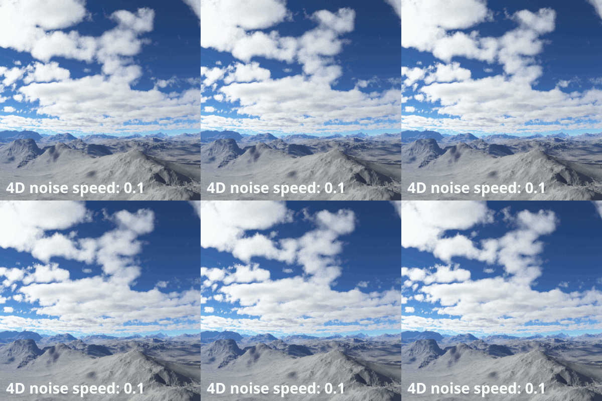
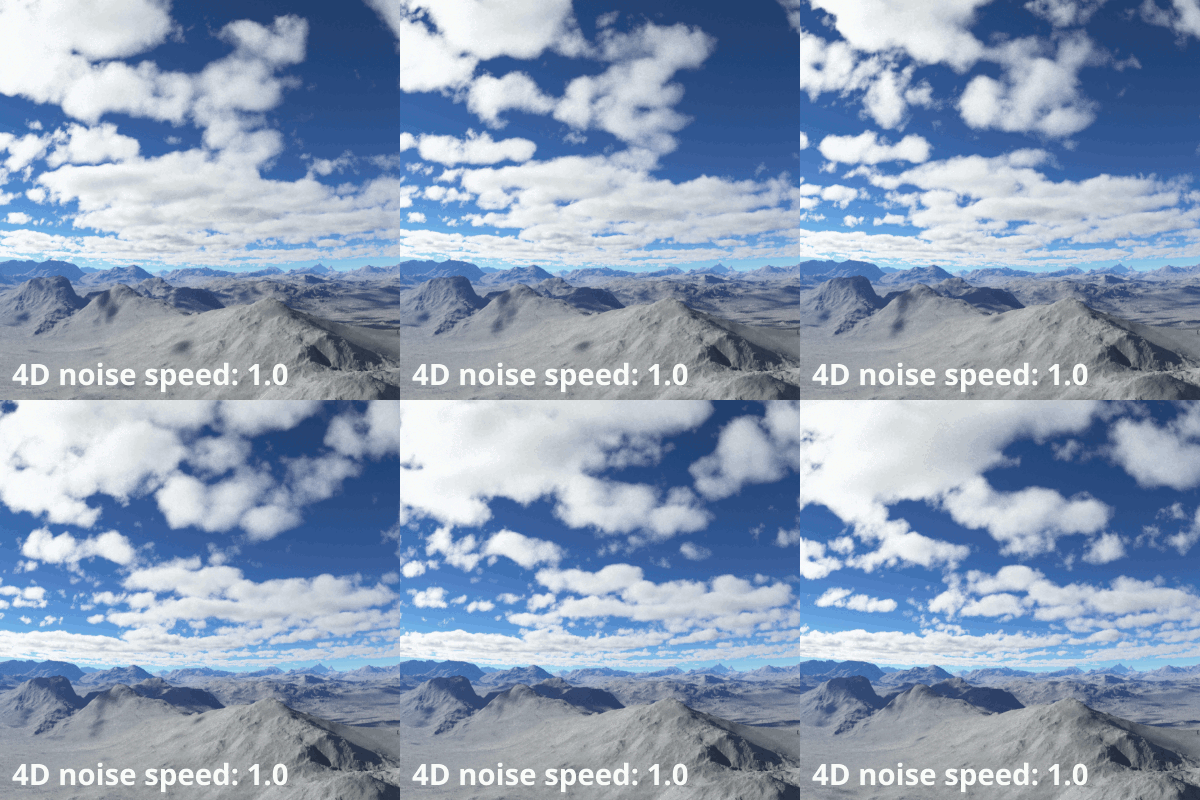
- 4D noise speed: This setting controls how quickly the noise evolves. Higher values generate more rapid change over time; in other words, the higher the value, the greater the change from one frame to the next.
- Reference frame number: This is the frame at which changing the 4D noise speed value has no effect. For example, if the reference frame value is 1, then frame 1 will look the same no matter what the 4D noise speed value is set to. All other frames are calculated according to the time difference from this frame. The shape of the noise depends on the time difference multiplied by the 4D noise speed value.
Legacy Example Movies[edit]
Noise Flavour
| Distort by normal |
Lead-in warp effect |
Lead-in warp amount | |||
| Less warp at feature scale |
Allow vertical warp |
Literally, to change the position of something. In graphics terminology to displace a surface is to modify its geometric (3D) structure using reference data of some kind. For example, a grayscale image might be taken as input, with black areas indicating no displacement of the surface, and white indicating maximum displacement. In Terragen 2 displacement is used to create all terrain by taking heightfield or procedural data as input and using it to displace the normally flat sphere of the planet.
A shader is a program or set of instructions used in 3D computer graphics to determine the final surface properties of an object or image. This can include arbitrarily complex descriptions of light absorption and diffusion, texture mapping, reflection and refraction, shadowing, surface displacement and post-processing effects. In Terragen 2 shaders are used to construct and modify almost every element of a scene.
A single object or device in the node network which generates or modifies data and may accept input data or create output data or both, depending on its function. Nodes usually have their own settings which control the data they create or how they modify data passing through them. Nodes are connected together in a network to perform work in a network-based user interface. In Terragen 2 nodes are connected together to describe a scene.
A parameter is an individual setting in a node parameter view which controls some aspect of the node.
A vector is a set of three scalars, normally representing X, Y and Z coordinates. It also commonly represents rotation, where the values are pitch, heading and bank.
Literally, to change the position of something. In graphics terminology to displace a surface is to modify its geometric (3D) structure using reference data of some kind. For example, a grayscale image might be taken as input, with black areas indicating no displacement of the surface, and white indicating maximum displacement. In Terragen 2 displacement is used to create all terrain by taking heightfield or procedural data as input and using it to displace the normally flat sphere of the planet.
