Smooth Step Scalar
Overview[edit]
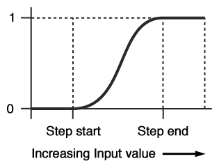
The Smooth step scalar node is a function node which can be used to create a smooth transition between values. It outputs a value between 0 and 1 depending on the Input value and the Step start and Step end values. The two step values define a range of values between which the output value is smoothly interpolated between 0 and 1, like a gradient. See the graph below for an idea of how the function works:
When the Input value is less than the Step start value the output is 0.
When the Input value is between the Step start and Step end values, it will be some smoothly interpolated value between 0 and 1.
When the Input value is greater than the Step end value the output is 1.
The Smooth step scalar is very useful for creating smooth transitions between two values. Having smooth transitions is important when creating procedural textures and the like because sharp transitions (such as those created by the Hard step scalar node) can cause undesirable visual artifacts such as aliasing (otherwise known as "jaggies"), or popping of textures in animations.
Setings:
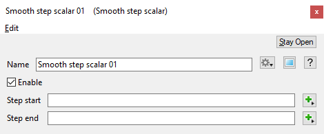
- Name: This setting allows you to apply a descriptive name to the node, which can be helpful when using multiple Smooth Step Scalar nodes in a project.
- Enable: When checked, the node is active and the smooth step operation will take place. When unchecked the values assigned to its Main Input, if any, are passed through, otherwise a value of 0 is passed through.
- Step start: The value defining the start of the smooth transition range, as in the graph above. This value becomes the minimum value, or 0.0, of the gradient. All values below this value become 0.0 .
- Step end: The value defining the end of the smooth transition range, as in the graph above. This value becomes the maximum value, or 1.0, of the gradient. All values above this value become 1.0 .
Error conditions:
- It is an error for there to be no input value. In that case 0 is output from the node.
- It is an error for there to be no Step start value. In this a value of 0 is used for the step start parameter.
- It is an error for there to be no Step end value. In this a value of 1 is used for the step end parameter.
Fun with Step Scalar Nodes[edit]
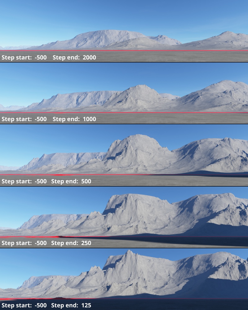
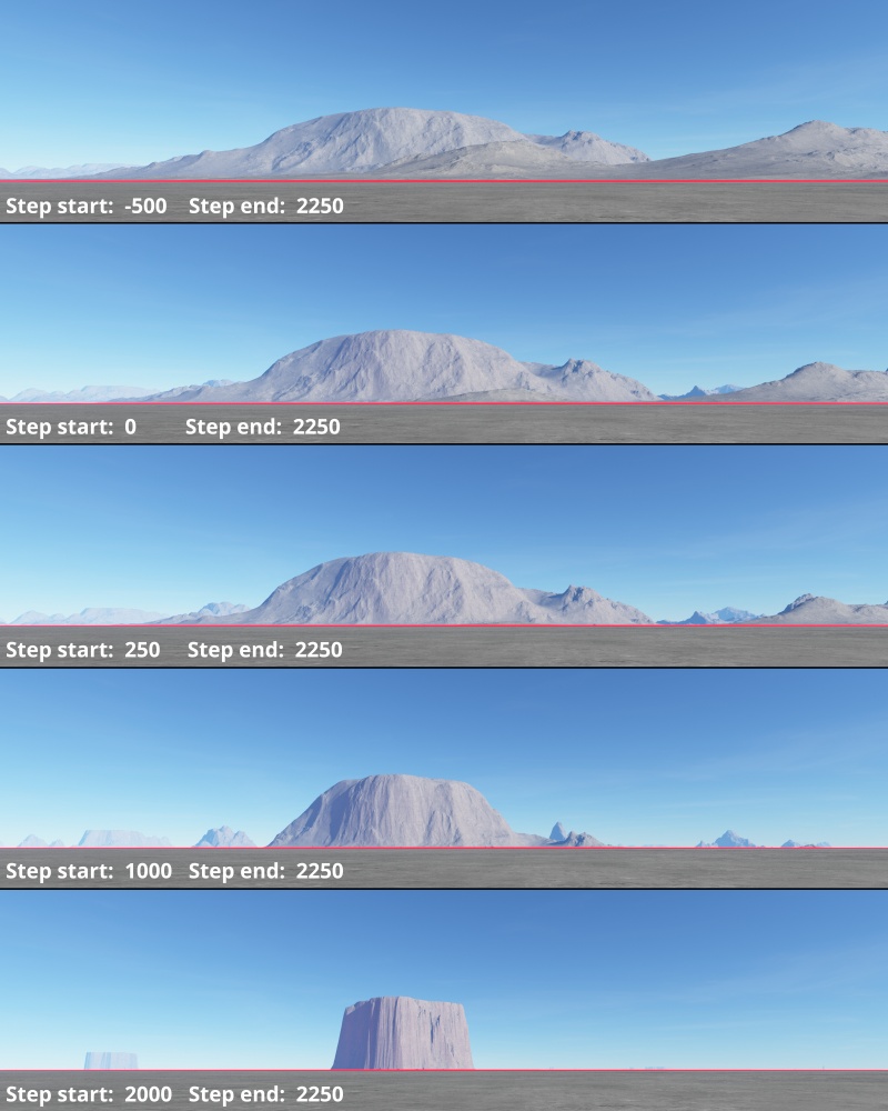
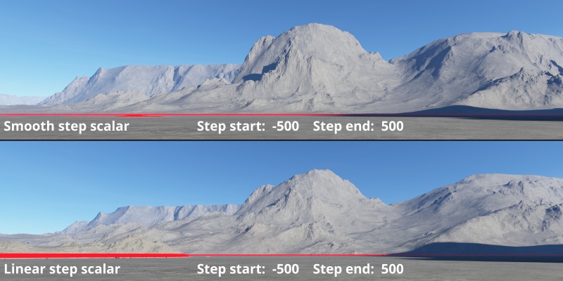
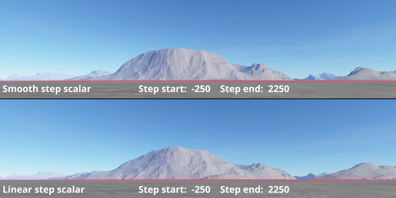
In the examples below, you can see the difference between using a Smooth step scalar node or a Linear step scaler node.
A scalar is a single number. 1, 200.45, -45, -0.2 are all examples of scalar values.
A single object or device in the node network which generates or modifies data and may accept input data or create output data or both, depending on its function. Nodes usually have their own settings which control the data they create or how they modify data passing through them. Nodes are connected together in a network to perform work in a network-based user interface. In Terragen 2 nodes are connected together to describe a scene.
A parameter is an individual setting in a node parameter view which controls some aspect of the node.
