Subsurface Scattering
Look development: Subsurface Scattering
A PDF version of this document is available:
Media:Terragen_look_development_subsurface_scattering_v08.pdf
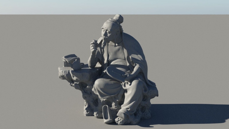
The model we will use as support for the Look Development series
Most shaders in Terragen allow you simulate light bouncing off a surface, but some of them can also simulate light traveling inside an object.
This guide is about using the Glass shader to simulate light traveling through and scattering inside objects.
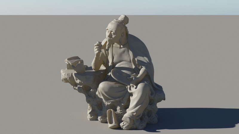
The Default shader (above and below) can handle most materials. It can also simulate thin object translucency, such as leaves or paper:
Default shader with yellow translucency
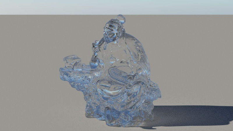
To achieve a proper subsurface look, we will need a Glass shader ![]()
We will also have to change the renderer to Path tracer 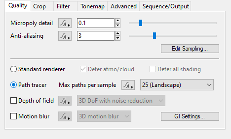
Glass shader (default settings)
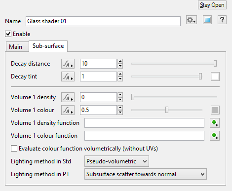
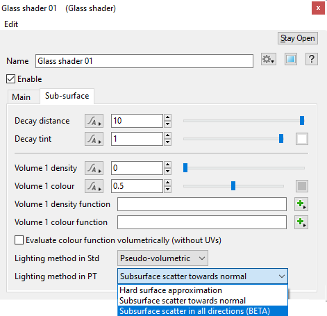
In the Glass shader properties window is a Sub-surface tab. This is where we will adjust how light behaves inside the object.
The Decay distance is how far (in meters) the light will travel before reaching the Decay tint.
A pure red Decay tint will mean that the material will absorb all wavelength except the red.
For a realistic result, you might want to use subtle colors: see how rich a pale red becomes as we lower the Decay distance.
The Volume density will define how “dense” the interior of the model is: this is meant to simulate all the microscopic particles for the light to bounce off inside the object.
The more particles, the more bounces, thus the more subsurface scattering.
Think of it as the amount of droplets in a cloud or the quantity of air bubbles in ice.
Here is the same pale red used for the Volume colour. See how it behaves when increasing the Volume density.
To achieve a believable subsurface effect, we need to balance both the Volume density and Decay distance:
The more we reduce the Decay distance, the stronger the Volume density affects the object.
If the Decay distance doesn’t allow the light to travel farther away, it has to dissipate its energy inside the object.
This is why we need to think how far the light would really travel inside a given material.
Gemstones, ice, marble, wax or human skin won’t have the same Decay distance or Volume density.
The look of the subsurface will therefore highly depend on the scale of the model.
Lighting method in PT (Path Tracer) gives us two subsurface options.
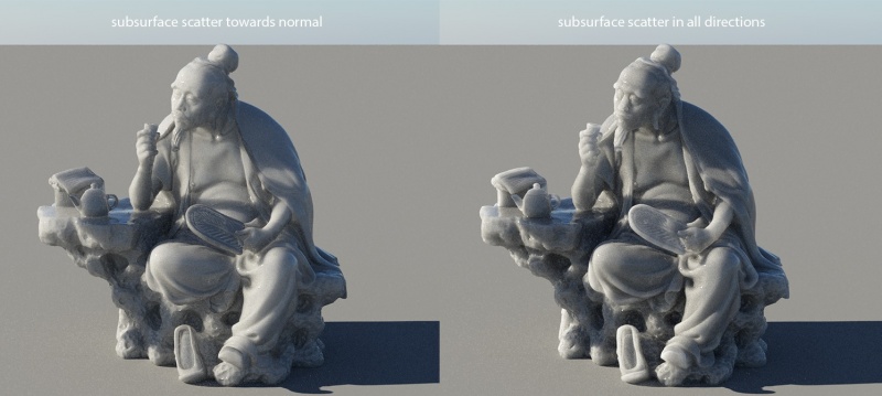
Subsurface scatter in all directions is designed to accurately scatter light inside a closed object.
Subsurface scatter toward normal is a faster method designed for simple, flat objects, such as water surfaces
Note how Subsurface in all directions gives a more natural look as the light bounces inside the object, not only towards its surface.
Light passes more realistically through edges and thin parts of the object, and it may also create deeper shadows where appropriate.
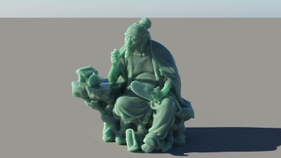
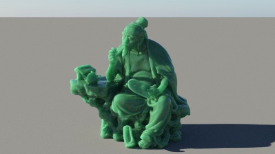
Now let’s add some colour: we change the Decay tint and the Volume colour to different green values:
Decay tint will determine the colour of the material when the light travels through it.
Volume colour will define the colour of the material when the light bounces inside of it.
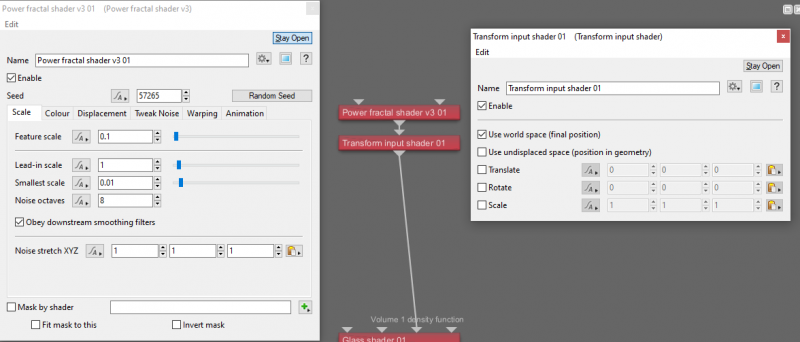
Here we create a fractal noise and plug it into the Volume density function.
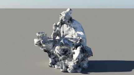
You will have to create a Transform input shader and change it to Use world space. This applies the noise in 3D space rather than mapping it onto the UV of the surface.
You can also input textures with an Image map shader.
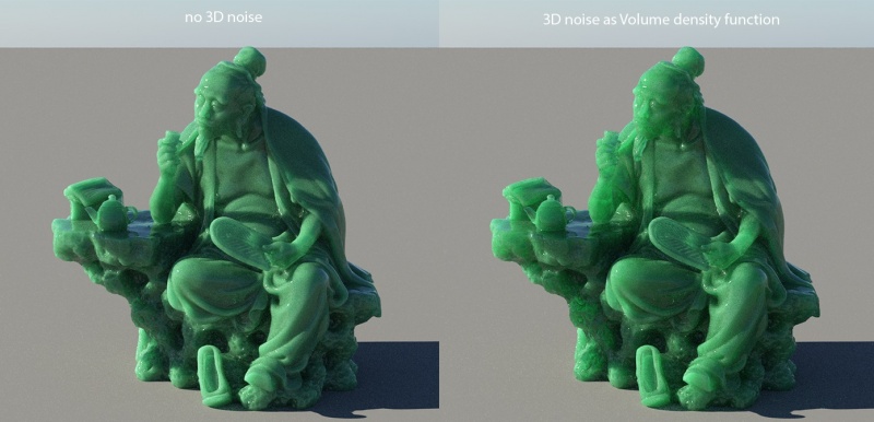
Here is the difference with the fractal noise applied in the Volume density function.
Note the areas where the light travels through the material, making some areas less homogeneous.
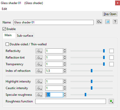
Back to the main tab of the Glass shader, we now take a look at the Specular roughness.
The Specular roughness plays a more subtle, yet essential role to achieve a believable material.
It will simulate the microscopic imperfections on the surface of the object, making it more or less “polished”. As this controls specular transmission as well as reflection, it will affect the sharpness of the refractions.
Note how the teapot handle takes a more “gummy” appearance as the roughness increases.
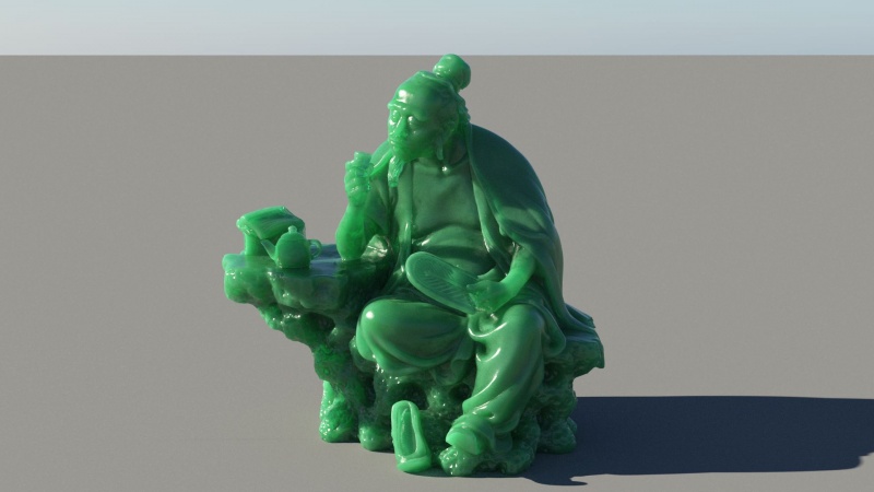
Increasing the Anti-aliasing from 3 to 6 and the Max paths per sample to 36 gives us a pretty decent image.
The Volume Colour function can also be mapped, using both 3D noise or texture map.
However there is an important parameter to consider as well: Evaluate colour function volumetrically.
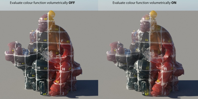
This plays a key role if you want to use a texture to drive the look of your subsurface: it will compute the colour as the ray travels inside the object:
In this example, a texture is projected (on the Z axis) onto the object and plugged into the Volume colour function.
We can clearly see the difference between the two colour evaluations. The first one keeps the texture colour from the surface, while the second one evaluates the texture at points inside the volume.
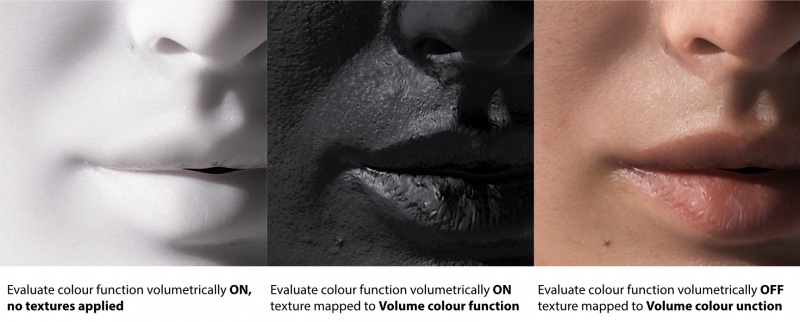
Mapping a texture using the Object UV instead will give quite a different result:
In order to use textures mapped onto the object UVs, Terragen needs to evaluate its surface.
Turning evaluate colour function volumetrically ON will result in a 3D evaluation (world space).
Even if, in a sense, trying to define a volume colour by a texture mapped onto a surface might seem like a weird idea, there are some cases (in particular skin shading) where you might want to use the object's UV mapping to drive subsurface effects.
This is why this feature is disabled by default.
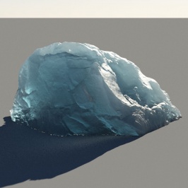
The Glass shader can cover pretty much any translucent/subsurface effect. Here is another example, using a rock object:
The Decay tint is set to a light blue colour and the Lighting method in PT to Subsurface scatter in all directions.
Reducing the Decay distance and increasing both the Volume density and the Specular roughness allow to create various types of ice:
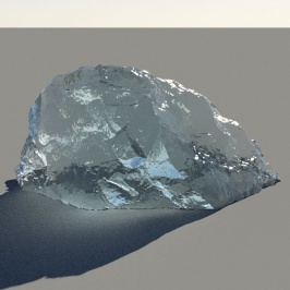
Clear, fresh ice means that light travels through it pretty much undisturbed: the Specular roughness is low, giving us a wet and shiny look, as well as sharp refractions.
The Decay distance is high and the Volume density is low, meaning that little subsurface scattering occurs.
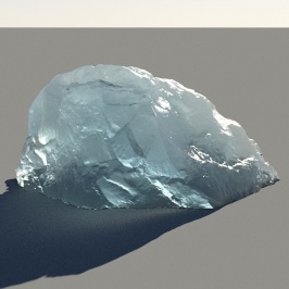
Older, salt water ice will have lots of impurities and air bubbles. Its surface will age as well, resulting in a rougher look.
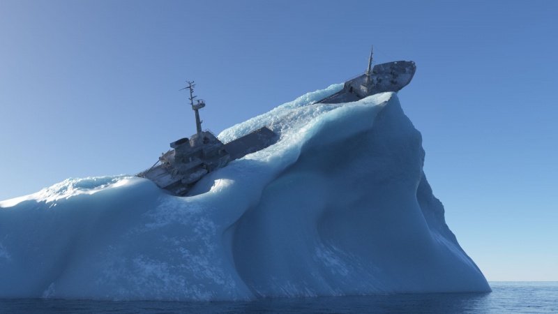
A high Specular roughness alongside a low Decay distance and a high Volume density gives the characteristic deep blue of icebergs:
Note how the ship affects the light scattering inside the iceberg.
General rendering guidelines:
Rendering true subsurface scattering is expensive.
When trying to increase quality and reduce noise, think of increasing Max paths per sample first. This will give Terragen more budget to spend on secondary rays,
resulting in cleaner material and lower render time than just increasing the Anti-aliasing.
Watch out for large Decay distance and huge Volume density, this will slow things down.
There are special cases where you might want longer distances, such as the one above, but try to remember those values are in meters and have to make sense. Happy rendering!
 Guide by Bastien Muller
-revision 6- February 2020
A shader is a program or set of instructions used in 3D computer graphics to determine the final surface properties of an object or image. This can include arbitrarily complex descriptions of light absorption and diffusion, texture mapping, reflection and refraction, shadowing, surface displacement and post-processing effects. In Terragen 2 shaders are used to construct and modify almost every element of a scene.
A sample refers to a value or set of values at a point in time and/or space. The defining point of a sample is that it is a chosen value out of a continuous signal. In Terragen 2 it is usually a mathematical (procedural) function that is being sampled.
A parameter is an individual setting in a node parameter view which controls some aspect of the node.
