Sin Scalar
Contents
Overview[edit]
These nodes output the cosine, sine or tangent of the Input scalar. If you are using these functions for trigonomic calculations, rather than just for creating a wave shape or similar, you need to be aware that they expect Input values in radians rather than degrees. You can use the Degrees to radians scalar node for the conversion.
These nodes have no other settings apart from the Input node.
Settings:
- Name: This setting allows you to apply a descriptive name to the node, which can be helpful when using multiple Sin Scalar nodes in a project.
- Enable: When checked, the node is active, and when unchecked the node is ignored.
Fun with Sin Scalar[edit]
One way in which to use the Sin scalar function node is to create repeating lines or concentric circles. Masks can be applied to break up the repetition, and the results can be warped into non-linear or non-concentric patterns.
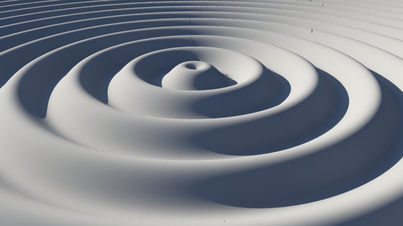
The following examples illustrate the Sin scalar function displacing a surface.
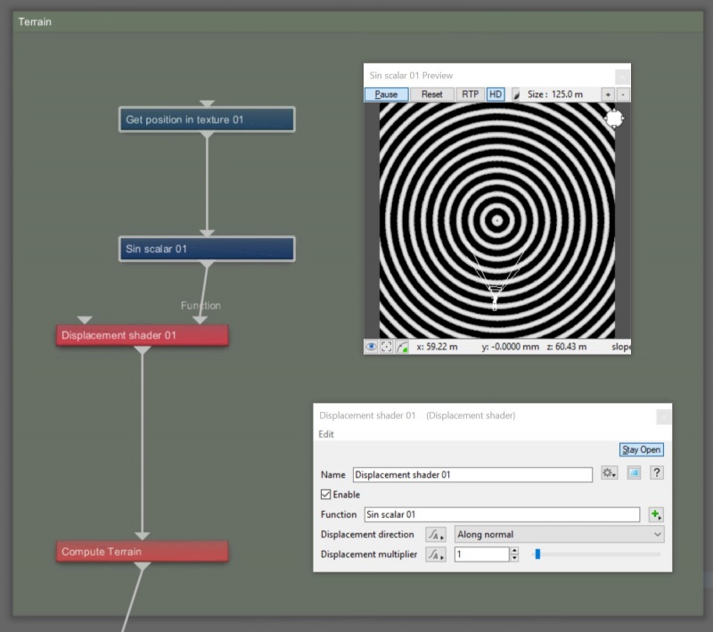
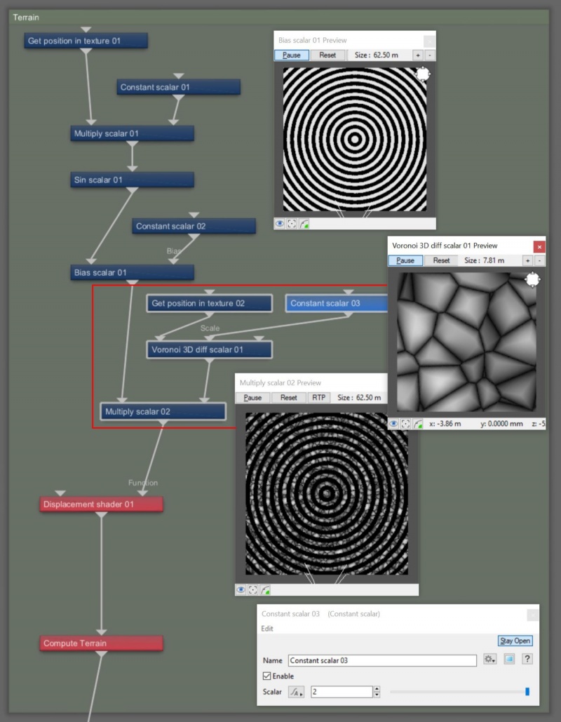
We’ll begin by adding a Displacement shader and a Sin scalar node to the project. The Sin scalar node needs data to work with, so we’ll add a Get Position in texture node so it can use the texture coordinates of the planet.
- Starting with the default project, left-click in the Node Network pane and drag a selection box around the “Simple shape shader”, “Fractal terrain”, and “Fractal warp shader” nodes, then press the “delete” key on your keyboard to delete them.
- Press the tab key or “N” key to open the Quick Node Palette window.
- Start typing the words “Displacement shader” and the closest match in the Node list will be highlighted.
- With “Displacement shader” highlighted, press the enter key to add it to the project.
- Drag a connection line from the “Output” of the Displacement shader node to the ”Main input” of the Compute Terrain node.
- Add a “Sin scalar” node and a “Get position in texture” node to the project in the same manner.
- Drag a connection line from the “Output” of the Get position in texture node to the ”Main input” of the Sin scalar node.
- Drag a connection line from the “Output” of the Sin scalar node to the ”Function” input of the Displacement shader.
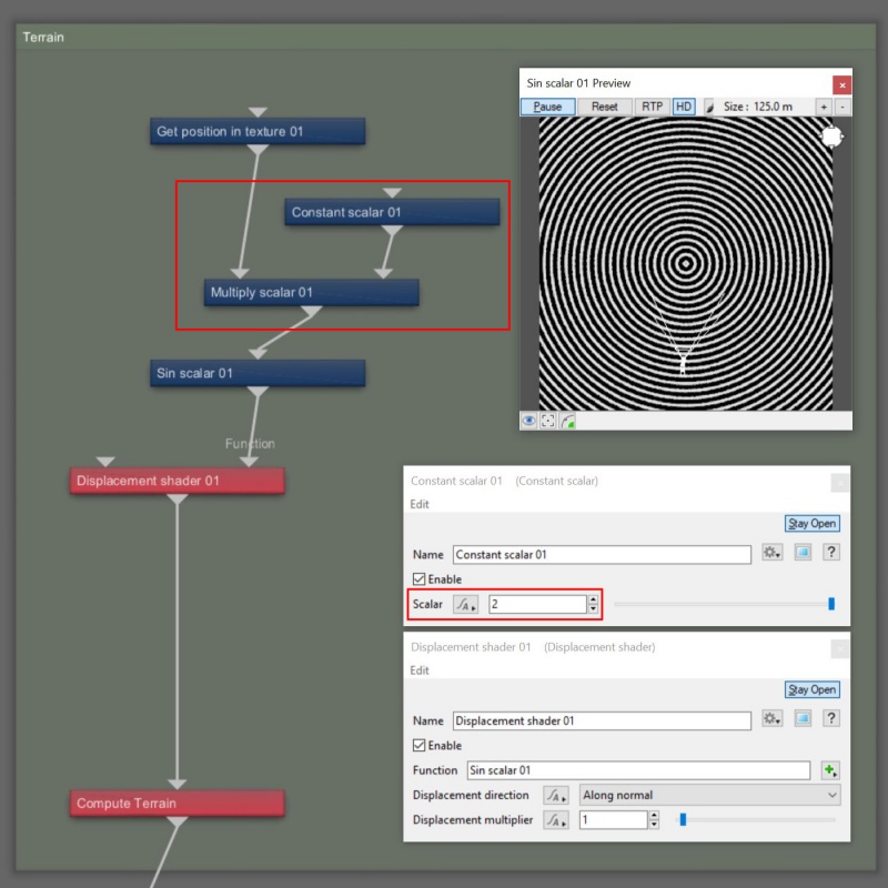
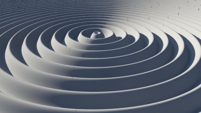
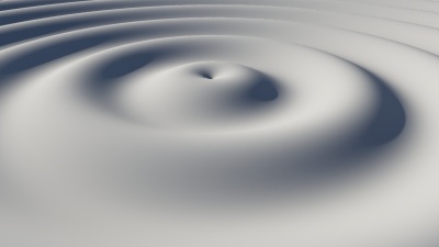
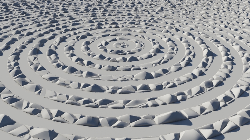
In the images above, you can see that already the Sin scalar node has created concentric rings about the origin of the project. You can increase or decrease the number of rings by multiplying the output from the Get position in texture node. Larger values increase the number of rings, while smaller values decrease them.
- Add a “Multiply scalar” node and a “Constant scalar” node to the project.
- Drag a connection line from the “Output” of the Get position in texture node to the “Main input” of the Multiply scalar node.
- Drag a connection line from the “Output” of the Multiply scalar node to the “Main input” of the Sin scalar node.
- Drag a connection line from the “Output" of the Constant scalar node to the “Input 2” of the Multiply scalar node.
- Double-click on the Constant shader node to open its dialog window.
- Set “Scalar” to “2”, to increase the number of rings, or “0.5” to decrease them.
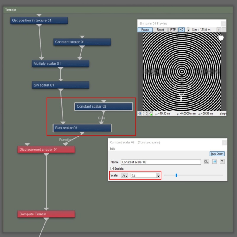
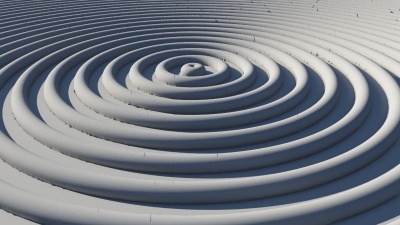
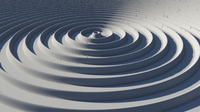
You can also change the profile or curvature of the rings using functions like Bias scalar or Gain scalar. These can be used to accentuate the high or low areas of the rings, and when used on terrain features such as a mountain, they can accentuate the rim of a mountain top or its foothills.
- Add a “Bias scalar” node and another “Constant scalar” node to the project.
- Drag a connection line from the “Output” of the Sin scalar node to the “Main input” of the Bias scalar node.
- Drag a connection line from the “Output” of the Bias scalar node to the “Function” input of the Displacement shader.
- Drag a connection line from the “Output” of the second Constant scalar node to the “Bias” input of the Bias scalar node.
- Double-click on the second Constant scalar node to open its dialog window.
- Set the “Scalar” value to “0.2”. Try other values to see how the curvature of the rings change. Recommended values are 0.2 to 0.8.
You can break up the concentric ring pattern by multiplying them by other function nodes such as Perlin and Voronoi noise patterns. These noise patterns require texture coordinate data which can be supplied by the Get position in texture node already in the project, and they have additional inputs for scale and seed value.
- Add another “Multiply scalar” node to the project.
- Drag a connection line from the “Output” of the Bias scalar node to the “Main input” of the Multiply scalar node.
- Drag a connection line from the “Output” of the Multiply scalar node to the “Function” input of the Displacement shader.
- Add a “Voronoi 3D diff scalar” node to the project.
- Drag a connection line from the “Output” of the Voronoi 3D diff scalar node to the “Input 2” of the second Multiply scalar node.
- Either drag a connection line from the “Output” of the existing Get position in texture node to the “Main input” of the Voronoi 3D diff scalar node, or add another Get position in texture node to the project and connect its output to the Main input of the Voronoi 3D diff scalar node.
- Add another “Constant scalar” node to the project. This will control the size of the Voronoi noise pattern.
- Drag a connection line from the “Output” of the Constant scalar node to the “Scale” input of the Voronoi 3D diff scalar node.
- Double-click on the Constant scalar node to open its dialog window.
- Set “Scalar” to “2”, or any other value you desire for the size of the noise pattern.
- If you like, you can add another Constant scalar node to the project to control the Seed value of the noise pattern. By changing the value assigned to the Seed parameter you change the noise pattern.
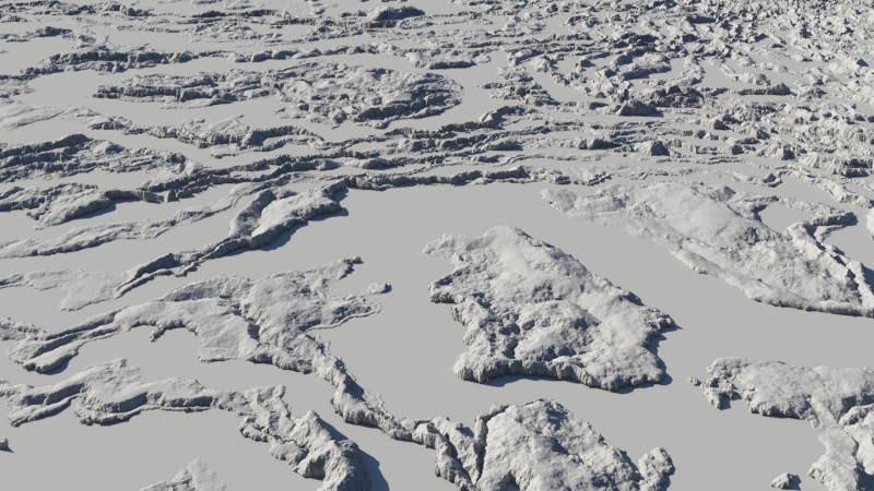
By warping the rings you can distort the concentric ring pattern and create interesting, organic, and more natural looking forms.
- Add a “Fractal warp shader” to the project.
- Drag a connection line from the “Output” of the Fractal warp shader to the “Function” input of the Displacement shader.
- Drag a connection line from the “Output” of the Multiply scalar node to the “Main input” of the Fractal warp shader.
- Double-click on the Fractal warp shader node to open its dialog window.
- Experiment with the Fractal warp shader parameters and see how they warp the concentric circles into new shapes.
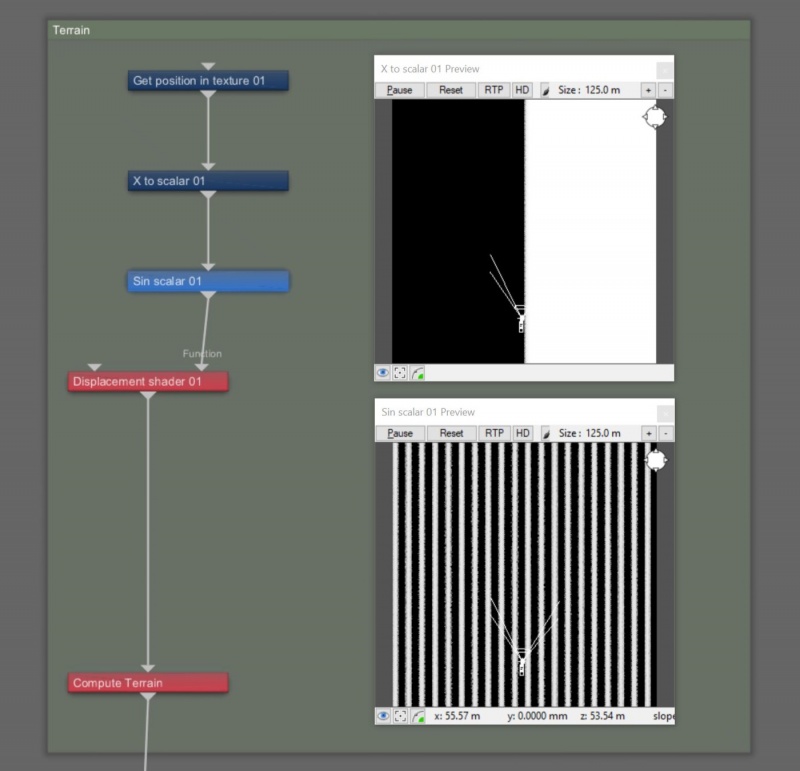
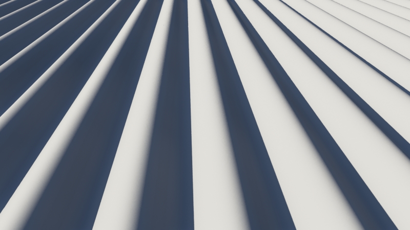
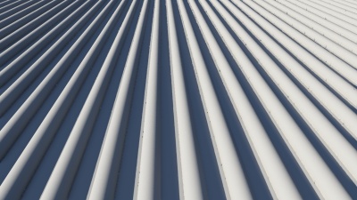
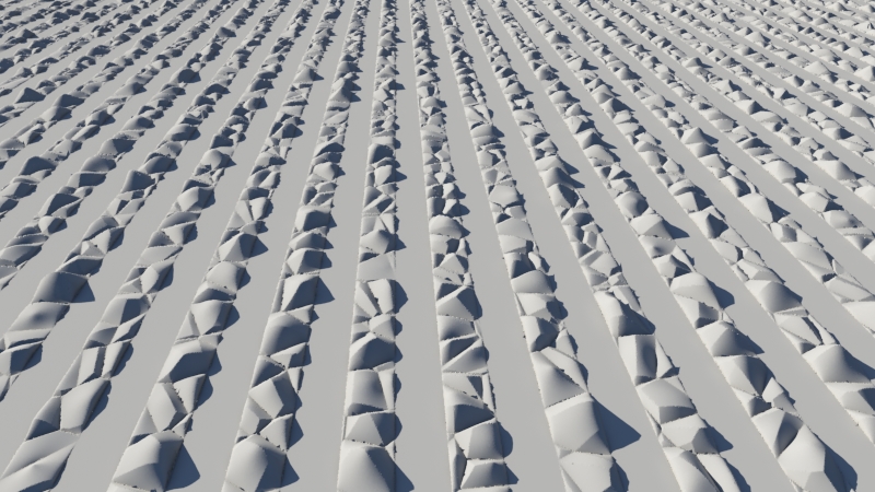
We can follow a similar procedure for creating parallel rows. Instead of directly connecting the Get position in texture node to the Sin scalar node we can insert a node to isolate one of the axis.
- Start with a new project, deleting the same three nodes in the Terrain group we did in the first step above.
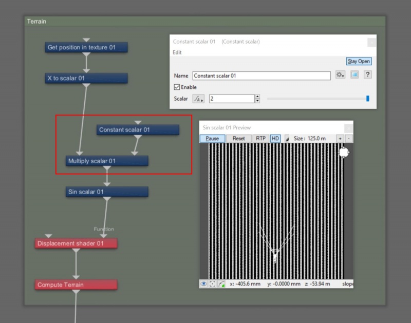
- Add a “Displacement shader" node, “Get position in texture” node, a “Sin scalar” node, and a “X to scalar” node to the project and connect them together as indicated in the image below.
Just like with the example using concentric rings, we can control the number of rows by multiplying the texture coordinate data before it gets to the Sin scalar node.
- Add a “Multiply scalar” node and a “Constant scalar” node to the project.
- Drag a connection line from the “Output” of the X to scalar node to the “Main input” of the Multiply scalar node.
- Drag a connection line from the “Output” of the Multiply scalar node to the “Main input” of the Sin scalar node.
- Drag a connection line from the “Output” of the Constant scalar node to the “Input 2” of the Multiply scalar node.
- Double-click on the Constant shader node to open its dialog window.
- Set “Scalar” to “2”, to increase the number of rings, or “0.5” to decrease them.
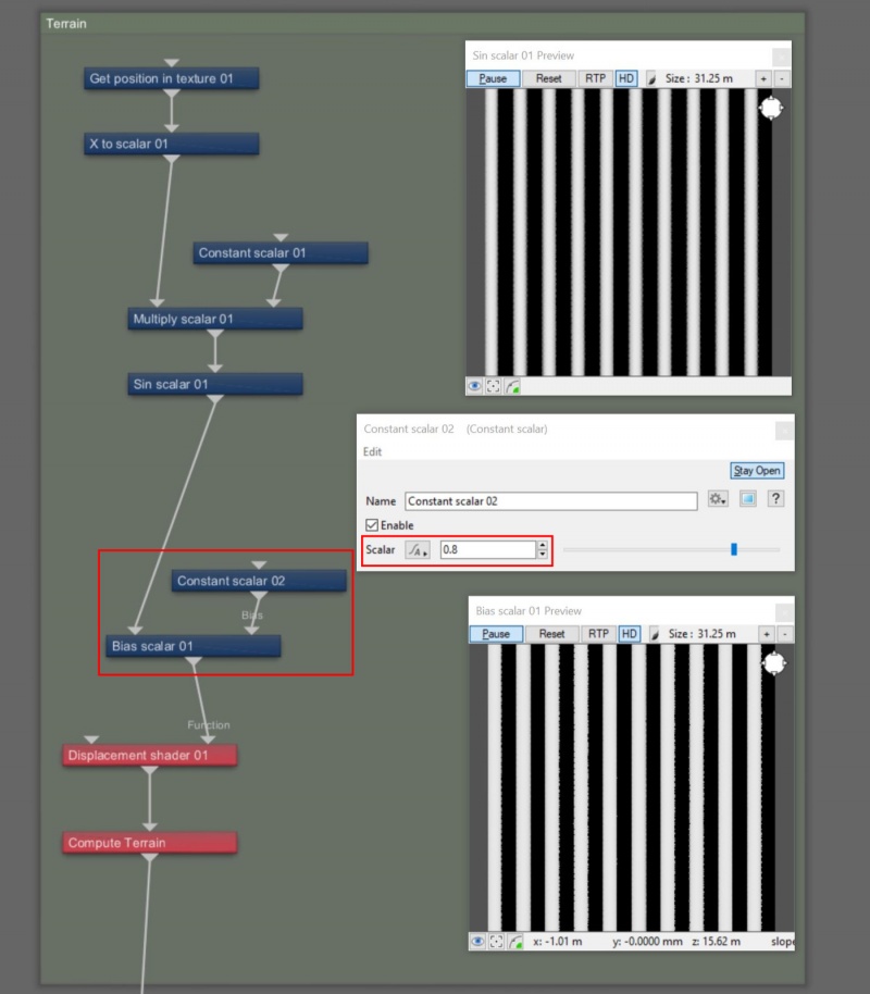
The profile or curvature of the rows can be manipulated in precisely the same way as with the concentric rings.
- Add a “Bias scalar” node and another “Constant scalar” node to the project, and connect them as indicated in the image below.
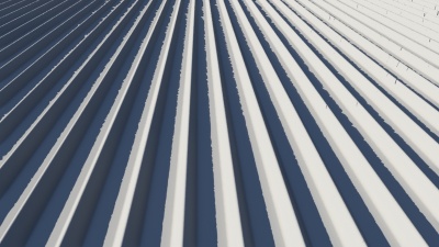
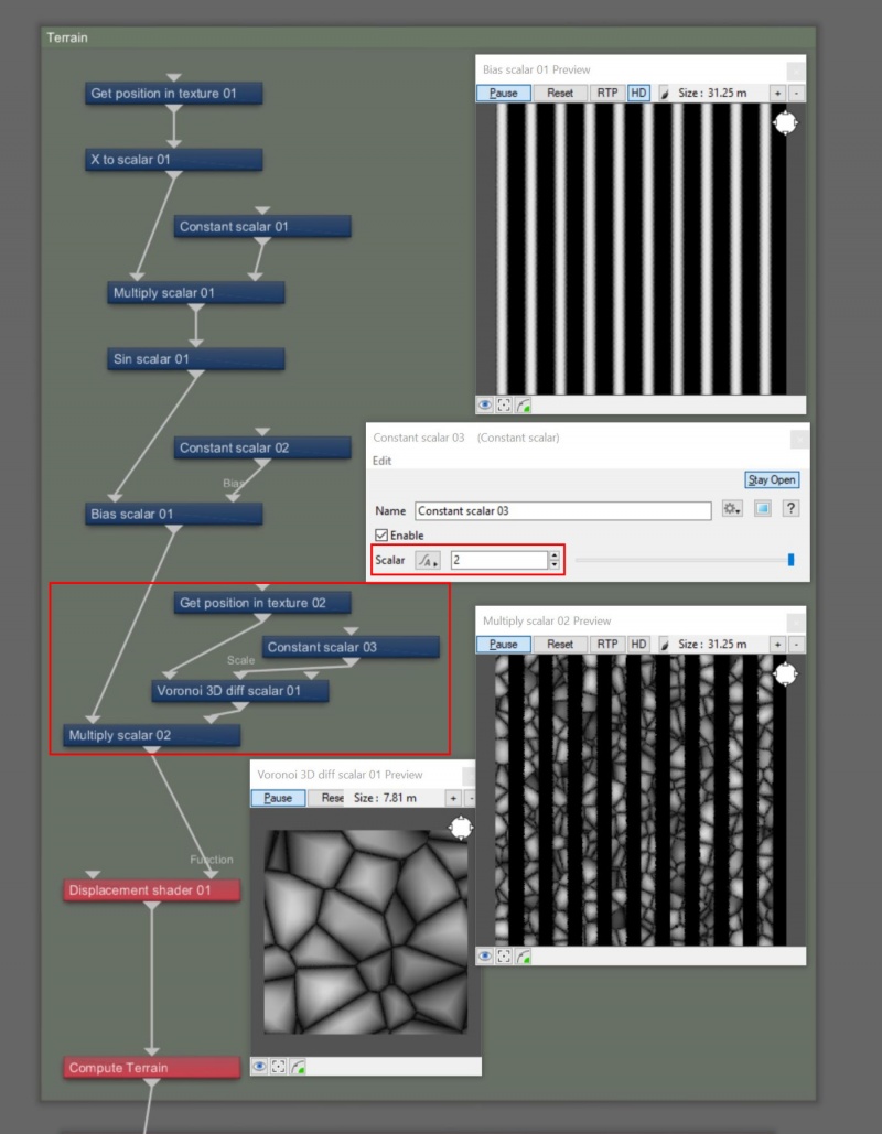
The parallel rows can be broken up by multiplying them with other function nodes, like Perlin noise and Voronoi noise.
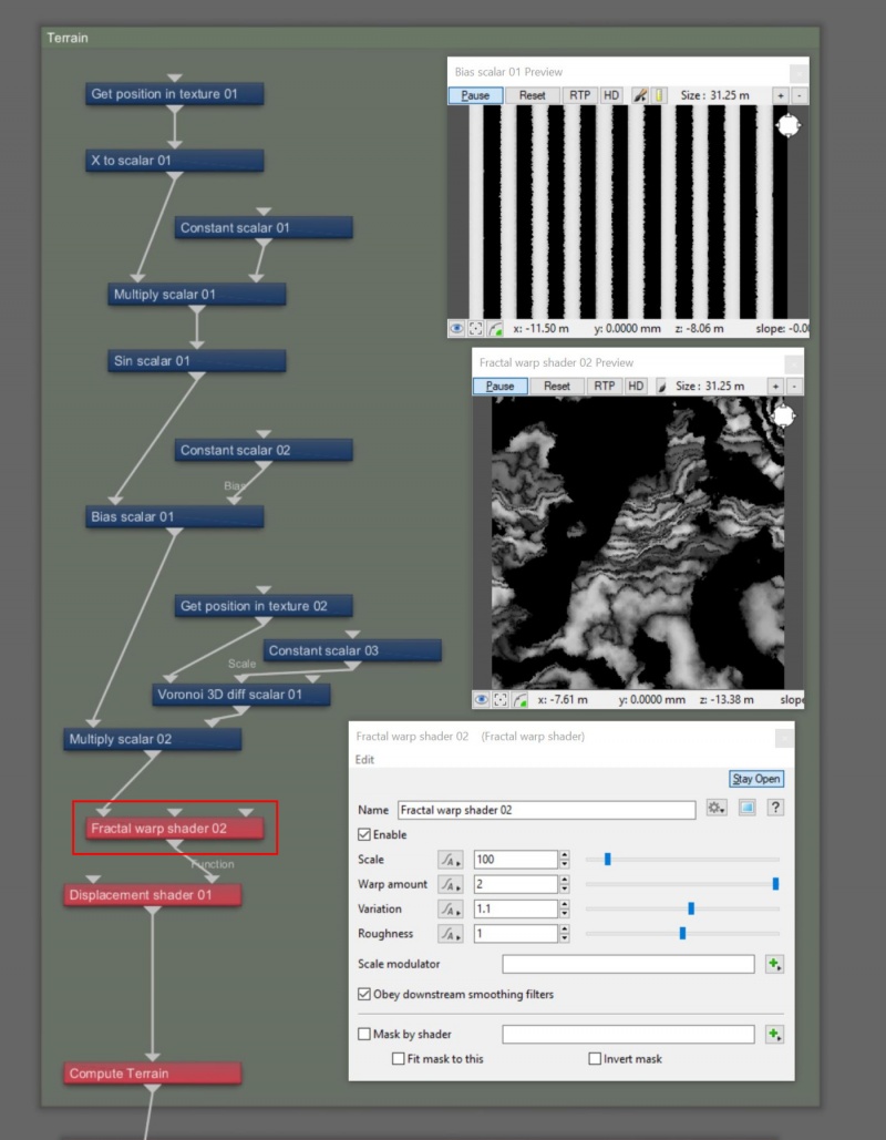
- Add a “Multiply scalar” node, a “Voronoi 3D diff scalar” node, another “Get position in texture” node, and a “Constant scalar” node to the project, and connect them as indicated in the image below.
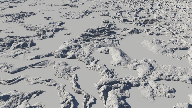
Finally, the broken up parallel rows can be warped, just as we did with the concentric rings.
- Add a “Fractal warp shader” node to the project and connect it as indicated in the image below.
A scalar is a single number. 1, 200.45, -45, -0.2 are all examples of scalar values.
A single object or device in the node network which generates or modifies data and may accept input data or create output data or both, depending on its function. Nodes usually have their own settings which control the data they create or how they modify data passing through them. Nodes are connected together in a network to perform work in a network-based user interface. In Terragen 2 nodes are connected together to describe a scene.
A shader is a program or set of instructions used in 3D computer graphics to determine the final surface properties of an object or image. This can include arbitrarily complex descriptions of light absorption and diffusion, texture mapping, reflection and refraction, shadowing, surface displacement and post-processing effects. In Terragen 2 shaders are used to construct and modify almost every element of a scene.
A parameter is an individual setting in a node parameter view which controls some aspect of the node.

