Get Position
Contents
Overview[edit]
The Get Positioin node provides the Position, in world space, of the current Render State. The Render State is affected by any shaders which were called before this function is called, among other things. Position is the current point on/in the surface/volume being rendered or sampled.
The input connection is not used by this node (consistent with all Get nodes).
When used in the context of displacement, for example in a function network that feeds a displacement shader, Position depends on where the node is connected with respect to other displacement shaders. This is because displacement shaders modify Position immediately.
When used in the context of providing colour and lighting to a surface, for example in a function network that feeds a shader's colour or luminosity, Position is always the "final position" after all displacement. This is because all displacements are performed before any shader's colour and lighting is calculated.
For many shading uses it is better to use Get Position in Texture, because that often provides a value that is consistent between displacement and colour contexts.
Settings:
- Name: This setting allows you to apply a descriptive name to the node, which can be helpful when using multiple Get Position nodes in a project.
- Enable: When checked, the node is active, and when unchecked the node is ignored.
Fun with Get Position[edit]
Let’s use the Get Position node to help define the location of a spherical cloud in our project!
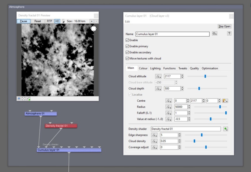
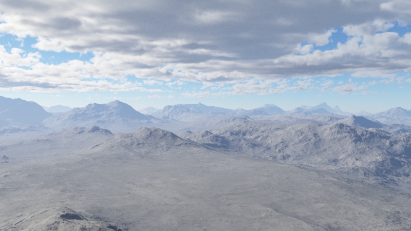
We’ll start by adding a generic cloud layer to the project.
- Click the “Atmosphere” button on the toolbar.
- Click the “Add Cloud Layer” button above the Node List.
- Select “Low-Level: Generic”.
A cloud layer’s volume is constrained within the Cloud depth and Radius settings.. You can think of these parameters as defining a cylinder in which the cloud exists. The cloud layer can not exceed these boundaries. In this example, we’ll create a spherical cloud with a radius of 1 kilometer, therefore we need to adjust these settings so that our spherical cloud can easily fit within.
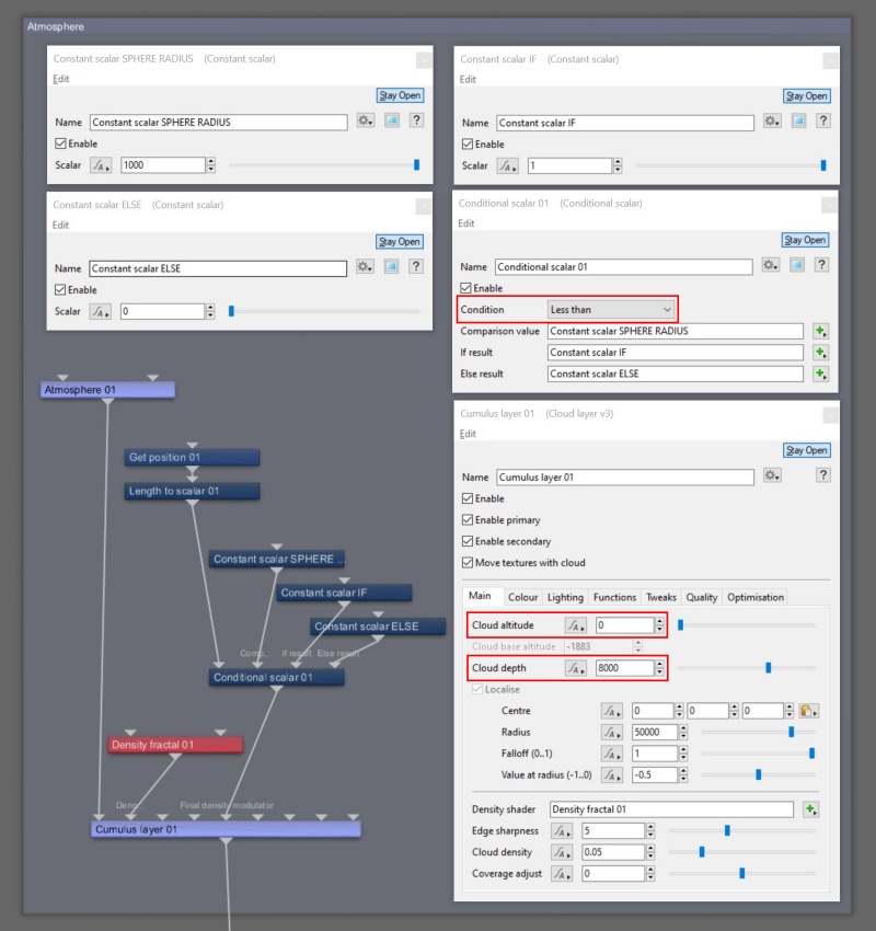
To make a spherical cloud shape we’ll compare the point being sampled by the renderer to see if it’s located within a certain radius and if it is we’ll allow it to render and if not, ignore it. To do that we’ll need to add a few nodes to the project. The Get Position node returns a vector for the location of the sampled point, and a Length to Scalar node will return the distance between the origin (0,0,0) and the sample point location. A Conditional scalar node compares that distance to a user defined value, in this case 1 kilometer, which can be supplied by a Constant scalar node. Two additional Constant scalar nodes contain the values to output from the Conditional scalar node, depending on whether the results are within 1 kilometer, or not.
- Click on an empty space in the Node Network pane to focus the program's attention there.
- Press the tab key or “N” key to open the Quick Node Palette window.
- Start typing the words “Get position” and the closest match in the Node list will be highlighted
- With “Get Position” highlighted, press the enter key to add it to the project.
- Add a “Length to scalar” node to the project in the same manner.
- Drag a connection line from the “Output” of the Get position node to the ”Main input” of the Length to scalar node.
- Add a “Conditional Scalar” node to the project.
- Drag a connection line from the “Output” of the Length to scalar node to the “Main input” of the Conditional scalar node.
- Add three “Constant scalar” nodes to the project.
- Double-click on the first Constant scalar node to open its dialog window.
- Set “Name” to “Constant scalar SPHERE RADIUS”, or something descriptive.
- Set “Scalar” to “500”.
- Drag a connection line from the “Output” of the Constant scalar to the “Comparison value” input of the Conditional scalar.
- Double-click on the second Constant scalar node to open its dialog window.
- Set “Name” to “Constant scalar IF”.
- Set “Scalar” to “1”.
- Drag a connection line from the “Output” of the Constant scalar node to the “If result” input of the Conditional scalar.
- Double-click on the last Constant scalar node to open its dialog window.
- Set “Name” to “Constant scalar ELSE”.
- Set “Scalar” to “0”.
- Drag a connection line from the “Output” of the Constant scalar node to the “Else result” input of the Conditional scalar.
- Double-click the Conditional scalar node to open its dialog window.
- Set “Condition” to “Less than”.
- Drag a connection line from the “Output” of the Conditional scalar node to the “Final density modulator” input of the Cloud layer.
- Double-click on the Cloud layer to open its dialog window.
- Set “Cloud altitude” to “0”. For this type of cloud layer, it positions the center of the cloud layer at 0 on the Y axis in world space.
- Set “Cloud depth” to “8,000”. For this type of cloud layer, the entire depth of the cloud is 8,000 metres; 4,000 metres of which are above 0 on the Y axis, and 4,000 metres are below.
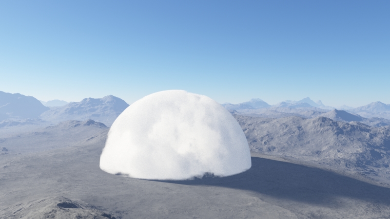
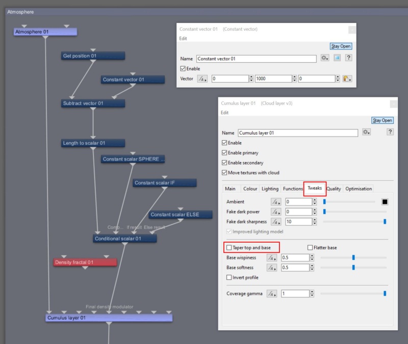
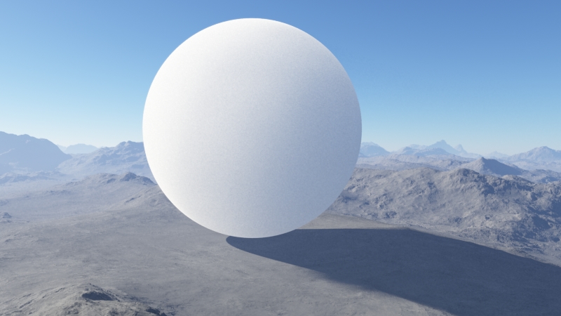
As you can see in the render above, the cloud layer is centered at 0 on the Y axis, and spherical in shape with half of its volume above the terrain and half below. To raise the entire cloud above the terrain we can modify the output from the Get position node by subtracting the value we used for the Sphere Radius, which was 1,000. The Length to scalar node uses this new value when determining the distance to the sample point.
- Add a “Subtract vector” node to the project.
- Drag a connection line from the “Output” of the Get position node to the “Main input” of the Subtract vector node.
- Drag a connection line from the “Output” of the Subtract vector node to the “Main input” of the Length to scalar node.
- Add a “Constant vector” node to the project.
- Double-click on the Constant vector node to open its dialog window.
- Set the “Vector” Y axis value to “1,000”.
- Drag a connection line from the “Output” of the Constant vector node to the “Input 2” of the Subtract vector node.
- Double-click on the Cloud layer to open its dialog window.
- Under the “Tweaks” tab, temporarily uncheck the “Taper top and base” checkbox. This disables the internal curve used to softly fade out the cloud layer near the top and bottom of its depth.
- Temporarily disconnect the connection line from the “Output” of the red Density fractal node to the “Density shader” input of the Cloud layer. This allows a cloud layer to fully fill the spherical volume, up to any Falloff values under the Main tab.
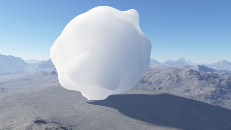
Now the spherical cloud is above the terrain. We can shape the cloud by once again modifying the output of the Get position node prior to the Length to scalar node determining the distance. This time we’ll add a bit of fractal noise to modulate where the Length to scalar node thinks the origin is.
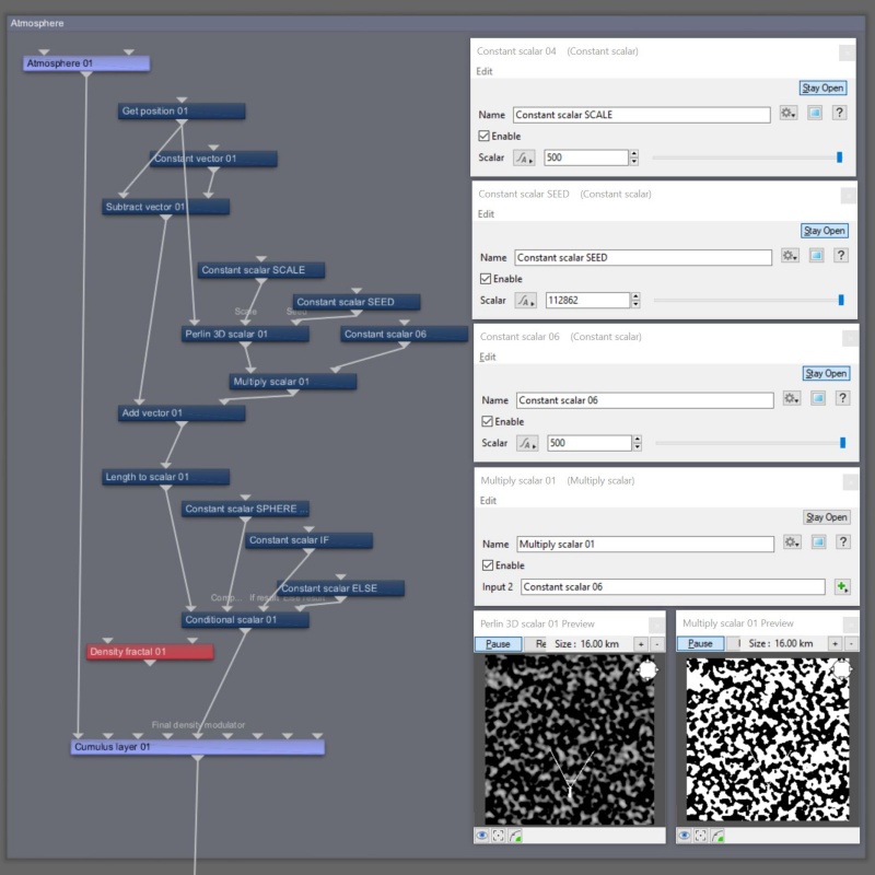
- Add an “Add vector” node to the project.
- Drag a connection line from the “Output” of the Subtract vector node to the “Main input” of the Add vector node.
- Drag a connection line from the “Output” of the Add vector node to the “Main input” of the Length to scalar node.
- Add a “Perlin 3D scalar” node to the project.
- Drag a connection line from the “Output” of the Get position node to the “Main input” of the Perlin 3D Scalar.
- Add two “Constant scalar” nodes to the project.
- Double-click on the first Constant scalar node to open its dialog window.
- Set “Name” to “Constant scalar SCALE”.
- Set “Scalar” to “500”. This will be used to set the feature scale of the noise pattern.
- Drag a connection line from the “Output” of the first Constant scalar node to the “Scale” input of the Perlin 3D scalar node.
- Double-click on the second Constant scalar node to open its dialog window.
- Set “Name” to “Constant scalar SEED”.
- Set “Scalar” to any number you want, for example “112862”. This value will be used as a starting point for the noise pattern.
- Drag a connection line from the “Output” of the second Constant scalar node to the “Seed” input of the Perlin 3D scalar node.
- Add a “Multiply scalar” node to the project. We’ll use this to increase the amplitude of the noise pattern values.
- Drag a connection line from the “Output” of the Perlin 3D scalar node to the “Main input” of the Multiply scalar node.
- Add a “Constant scalar” to the project.
- Double-click the Constant scalar node to open its dialog window.
- Set “Scalar” to “500”. Increasing this value will create larger deformations of the sphere shape.
- Drag a connection line from the “Output” of the Constant scalar node to “Input 2” of the Multiply scalar node.
Lastly, reconnect the Density fractal to the Cloud layer and enable the Taper top and base setting.
- Drag a connection line from the “Output” of the Density fractal to the “Density shader” input of the Cloud layer.
- Under the Tweaks tab, check the “Taper top and base” checkbox.
Special thanks to Hetzen and those who participated in this discussion on the Planetside Software forum, inspiring this Fun With section!
Literally, to change the position of something. In graphics terminology to displace a surface is to modify its geometric (3D) structure using reference data of some kind. For example, a grayscale image might be taken as input, with black areas indicating no displacement of the surface, and white indicating maximum displacement. In Terragen 2 displacement is used to create all terrain by taking heightfield or procedural data as input and using it to displace the normally flat sphere of the planet.
A shader is a program or set of instructions used in 3D computer graphics to determine the final surface properties of an object or image. This can include arbitrarily complex descriptions of light absorption and diffusion, texture mapping, reflection and refraction, shadowing, surface displacement and post-processing effects. In Terragen 2 shaders are used to construct and modify almost every element of a scene.
A single object or device in the node network which generates or modifies data and may accept input data or create output data or both, depending on its function. Nodes usually have their own settings which control the data they create or how they modify data passing through them. Nodes are connected together in a network to perform work in a network-based user interface. In Terragen 2 nodes are connected together to describe a scene.
In a graphical user interface (GUI) on a computer a toolbar is a row, column, or block of onscreen buttons or icons that, when clicked, activate certain functions of the program.
A vector is a set of three scalars, normally representing X, Y and Z coordinates. It also commonly represents rotation, where the values are pitch, heading and bank.
A sample refers to a value or set of values at a point in time and/or space. The defining point of a sample is that it is a chosen value out of a continuous signal. In Terragen 2 it is usually a mathematical (procedural) function that is being sampled.
A scalar is a single number. 1, 200.45, -45, -0.2 are all examples of scalar values.

