Recently, a Terragen Sky user asked us how to “render out all six faces of a cubemap?”
This is a great question, and since the answer is not immediately clear we thought it would make a good addition to our “Support Diaries” series of blog posts.
Cubemap images are used to create a cubemap texture, which is often used to simulate realistic environments in CGI, games, Virtual Reality (VR), and Augmented Reality (AR).
They can help simulate reflective surfaces without the heavy computation of ray tracing, or be used in physically based rendering (PBR) to provide realistic ambient lighting.
The Early Access version of Terragen Sky can render and save the Current View as a standard two dimensional image…
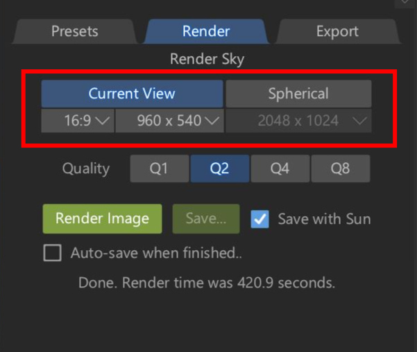
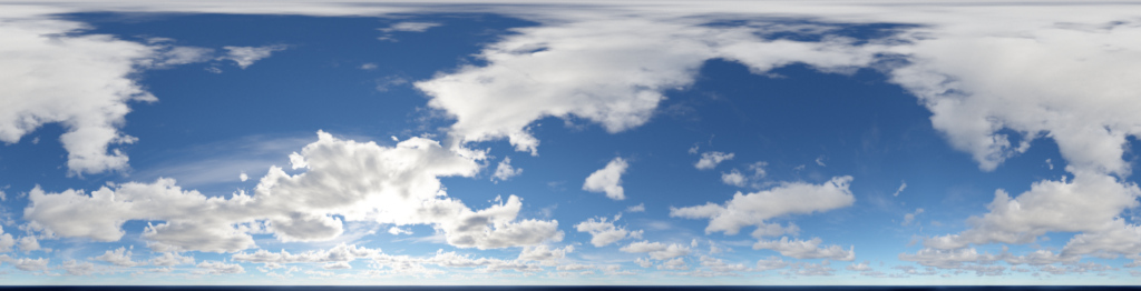
… or a Spherical “latlong” image, more properly referred to as an Equirectangular image.
Exporting a rendered image as a cubemap has not yet been implemented, but it’s on our list of features to include in future releases.
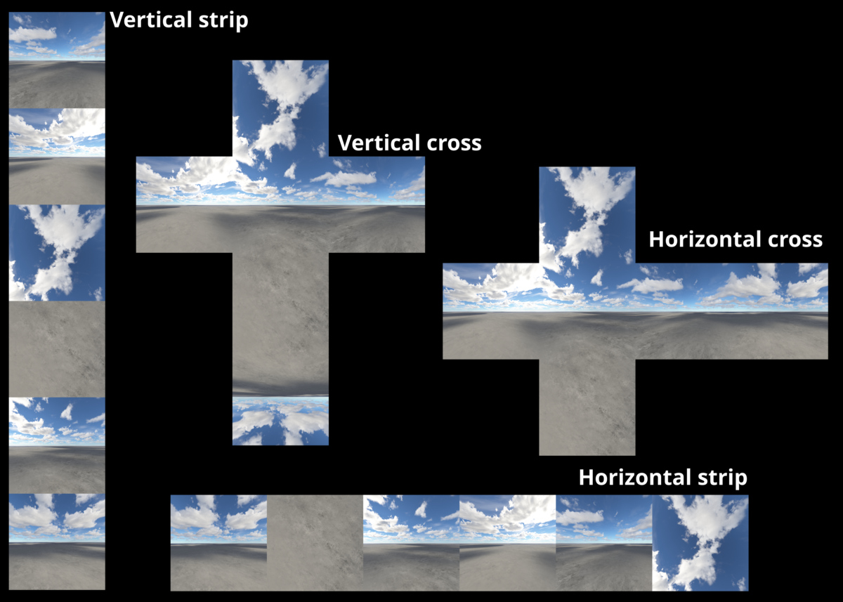
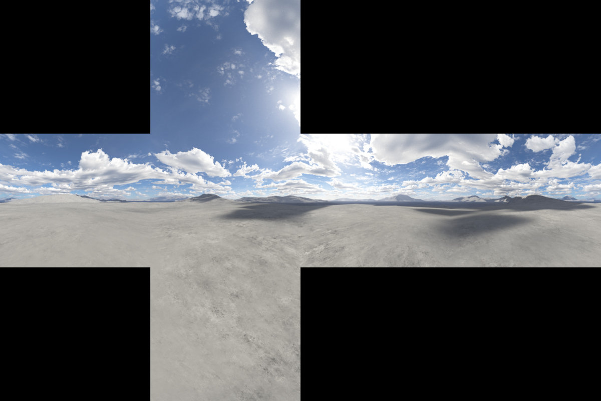
One reason why saving cubemaps hasn’t been implemented yet is that a number of different layouts exist, including horizontal or vertical crosses, and column or row layouts. Which layout to choose depends on what layouts are supported by the application you want to use the cubemap texture in.
So let’s dive into the process of creating the necessary images for a cubemap texture, once you’re happy with the look of your Terragen Sky environment.
Here’s a summary of the main steps we’ll need to take. Don’t worry, most of these steps are simple, and we’ve got some tools to share with you in order to help automate the process!
- Export the project from Terragen Sky.
- Load the project into Terragen 4.
- Create the cubemap cameras and a renderer.
- Render the cubemap images.
- Stitch the cubemap images together in a paint or compositing program, or dedicated script (like the one we’ve provided).
Exporting the Terragen Sky Project
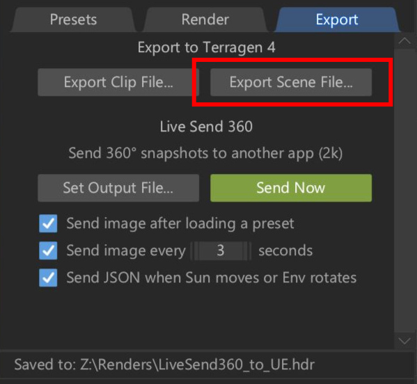
First, we’ll export the project from Terragen Sky in the TGD format so that Terragen 4 can open it. All you need to do is to go to the Export tab and click the “Export Scene File…” button. The exported project file will contain all the cloud layers and settings you’ve created, as well as cameras.
Load the Project in Terragen
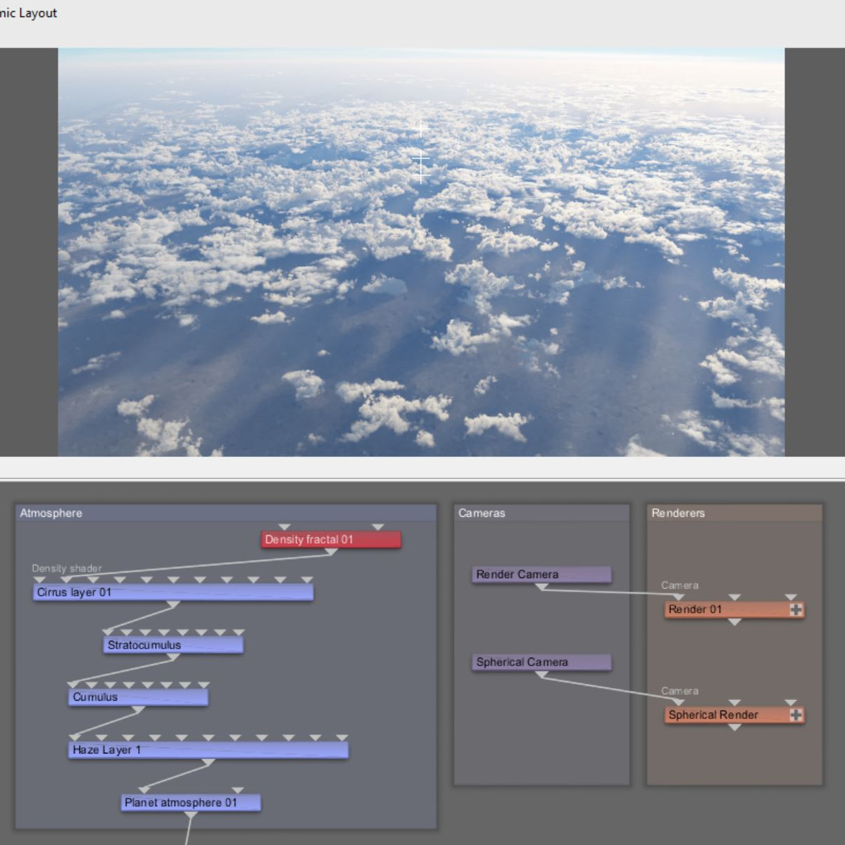
In Terragen, load the file via the main menu’s File > Open options. Notice that there are two cameras and two render nodes in the project, along with the cloud layers you created.
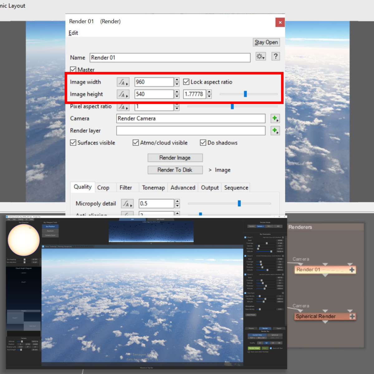
The render camera is a perspective type camera, and its position and rotation will match the camera from Terragen Sky. You may need to change the render node’s (Render 01) aspect ratio to match the Current View aspect ratio in Terragen Sky, but once you do the 3D Preview will update and its view will be the same as you saw in Terragen Sky.
Generating the GI Cache File
The spherical camera and render node allow you to render a 360 spherical image. We’ll use these two nodes to calculate and save a GI cache file for the entire scene. All we need for this example is one frame, so let’s create that right now by clicking on the GI Settings button at the bottom of the Quality tab, and then clicking on the “Write to GI cache file” button and setting an output path for the file.
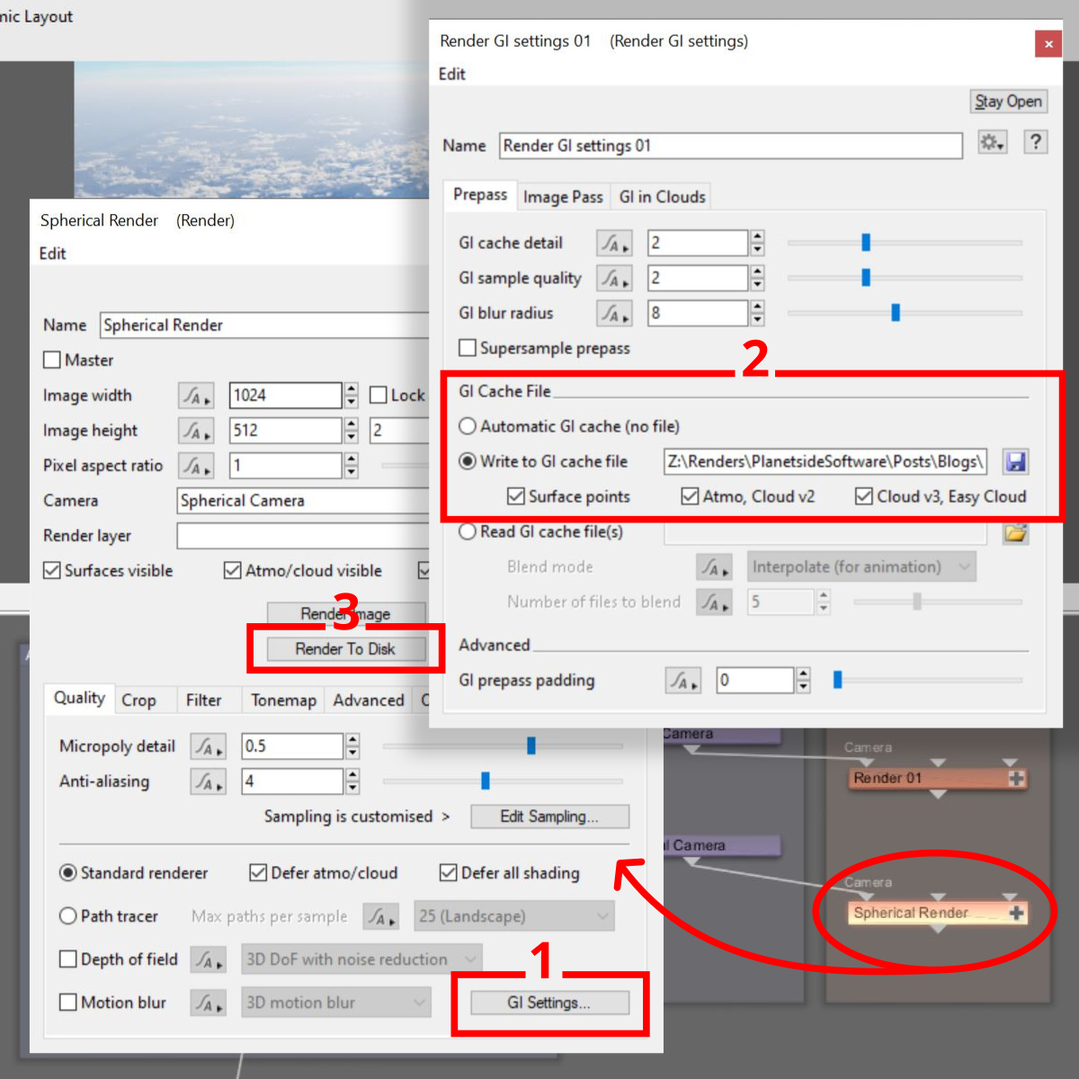
Then, click on the “Render to Disk” button to render and save the GI cache file. Note, we recommend this step even if you’re using the Path Tracer to render the cubemap images as the GI contributions affect the atmosphere as well.
Creating the Cubemap Camera and Render Nodes
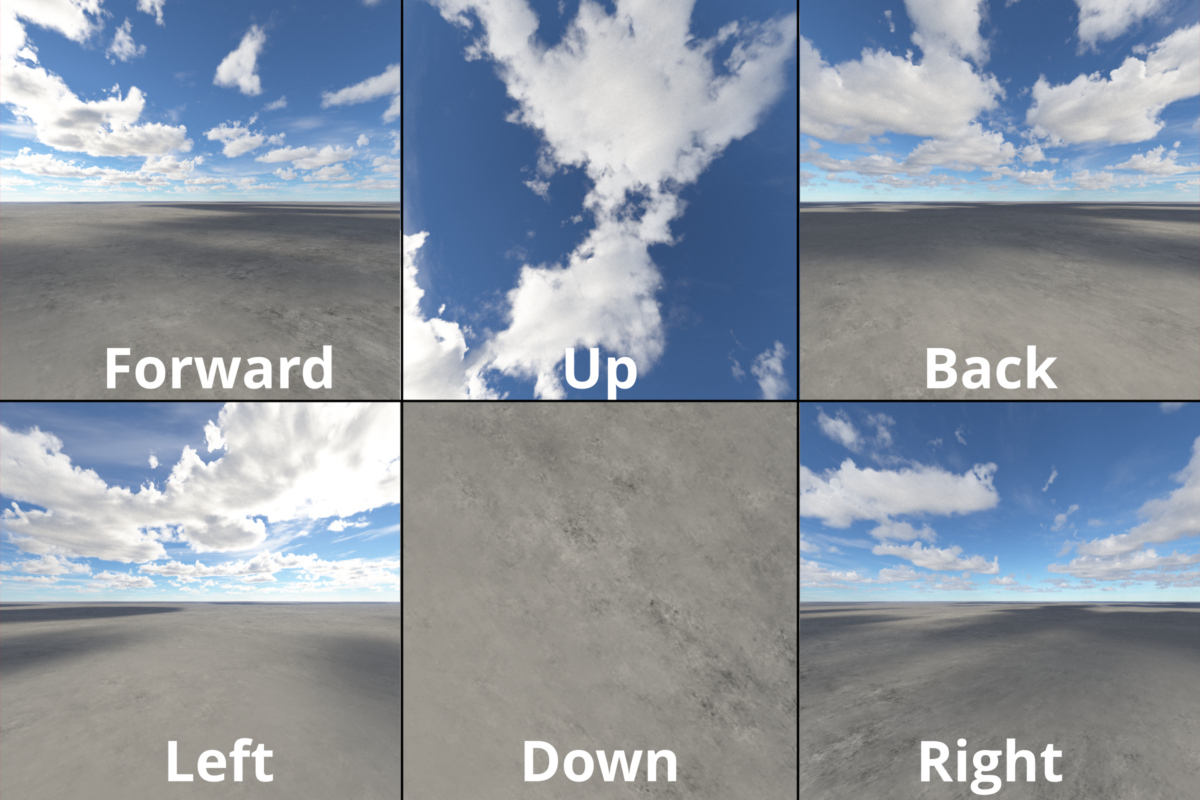
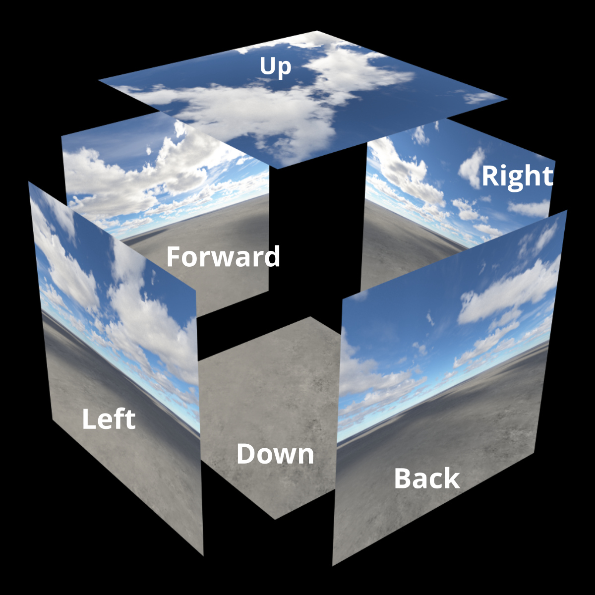
We need to create a camera for each cube face: Forward, Back, Left, Right, Up (Top) and Down (Bottom). Now you may be thinking, why not use one camera and keyframe its rotation to face in each direction? Of course you can, but that approach has several limitations, such as no longer being able to render animated sequences from each camera. Also, by using a dedicated camera for each cube face we can embed the name of the camera in the rendered output files by using the render variable ${CAMERA}. This ensures that each output image has a unique name, so only one render node is required for all the cubemap cameras.
Manual Approach
Let’s review the steps it would take to manually set up each of the six cameras and the renderer one at a time. To accomplish this you would:
- Add a new camera.
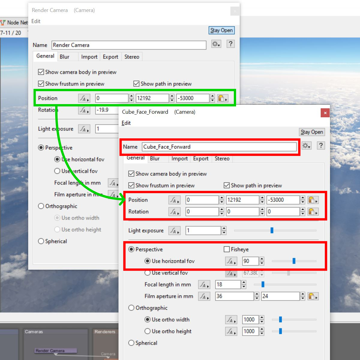
- Copy the “Position” parameter’s value from the source camera and paste it to the new camera’s position. In our example “Render Camera” is the source camera.
- Change the new camera’s “Rotation” parameter value by the appropriate amount. The Forward, Right, Back and Left camera’s “Heading” value would be incremented by 90 degrees, while the Up (Top) and Down (Bottom) camera’s “Pitch” value would be +90 degrees and -90 degrees respectively.
- Set the camera’s “Use horizontal fov” parameter value to 90.
- Optionally but highly recommended, rename the camera to something descriptive like “Forward”, “Back”, “Left”, etc.
Repeat the above steps for each of the five remaining cubemap cameras. Then we need to add a new render node for the cubemap cameras to use; thankfully we only need one using this approach.
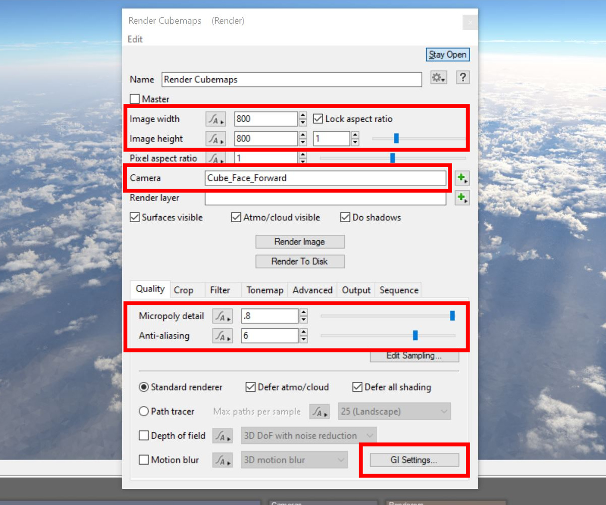
- Add a new renderer.
- Change its aspect ratio to 1.0 or optionally set the width and height to the same value, i.e. 1024 x 1024.
- Assign one of the cubemap cameras to the Camera input, i.e. Forward.
- Set the Micropoly detail and anti-aliasing values as desired.
- Click on the GI Settings button to open the Render GI Settings window.
- Click on the “Read GI cache file” button and select the GI cache file rendered from the spherical camera in the step above.
- Change the “Blend mode to “One file (exact filename)”
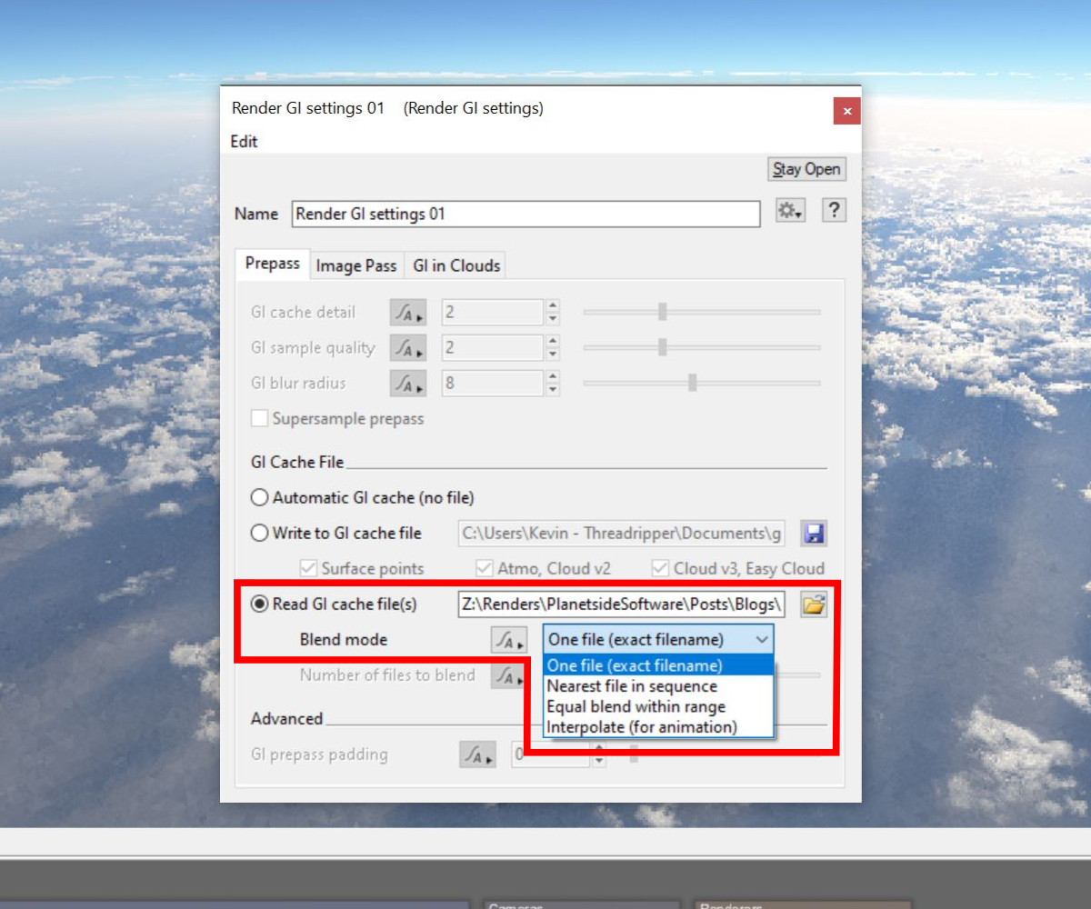
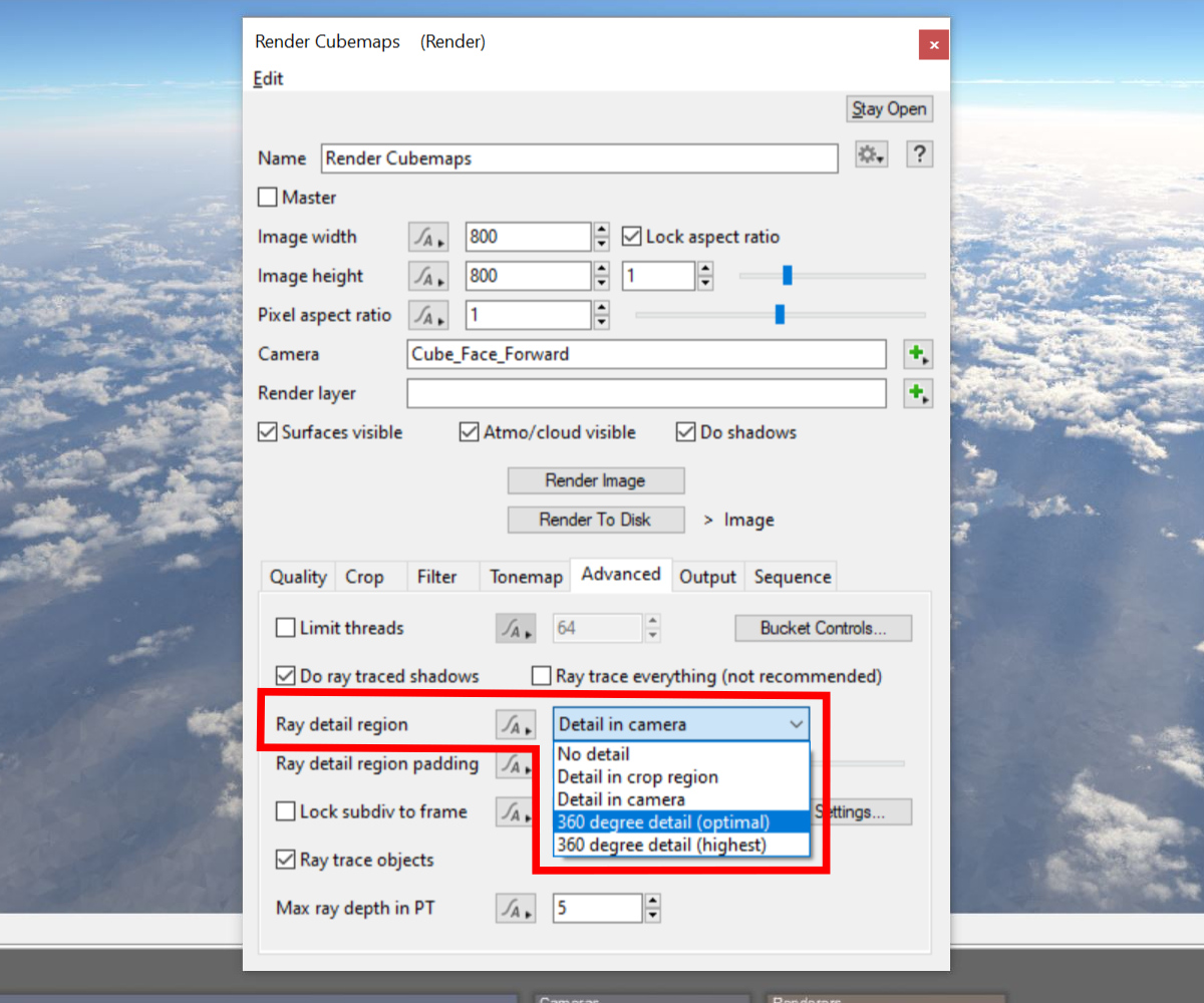
- Under the Advanced tab set the “Ray detail region” to “360 degree detail (optimal)”.
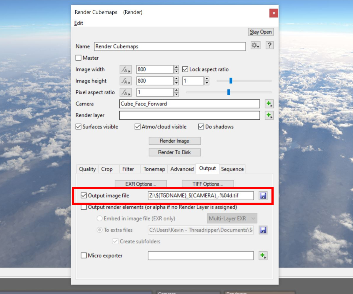
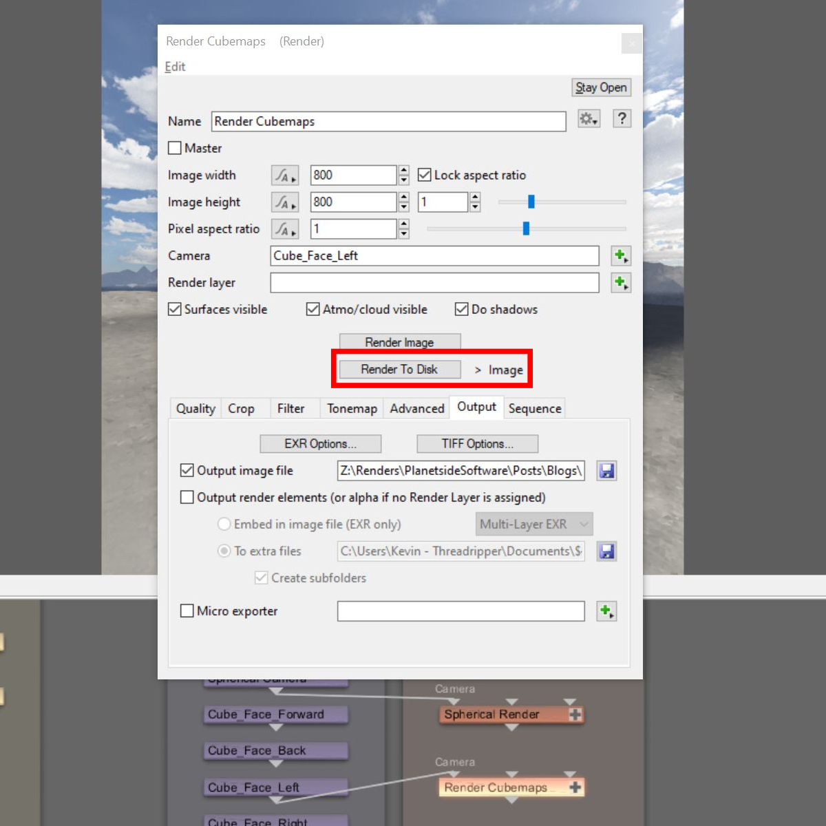
- Under the Output tab be sure to provide an “Output image file”. We highly recommend using Terragen’s built-in Render Output Variables when constructing the output file name. By including the variable ${CAMERA} as part of the filename, the output image will be unique and we will only need one render node for all the cubemap cameras.
Congratulations, the cubemap setup is complete! Let’s incorporate the step below so we don’t have to do it all over again the next time we want to setup cubemaps!
Semi-Manual Approach
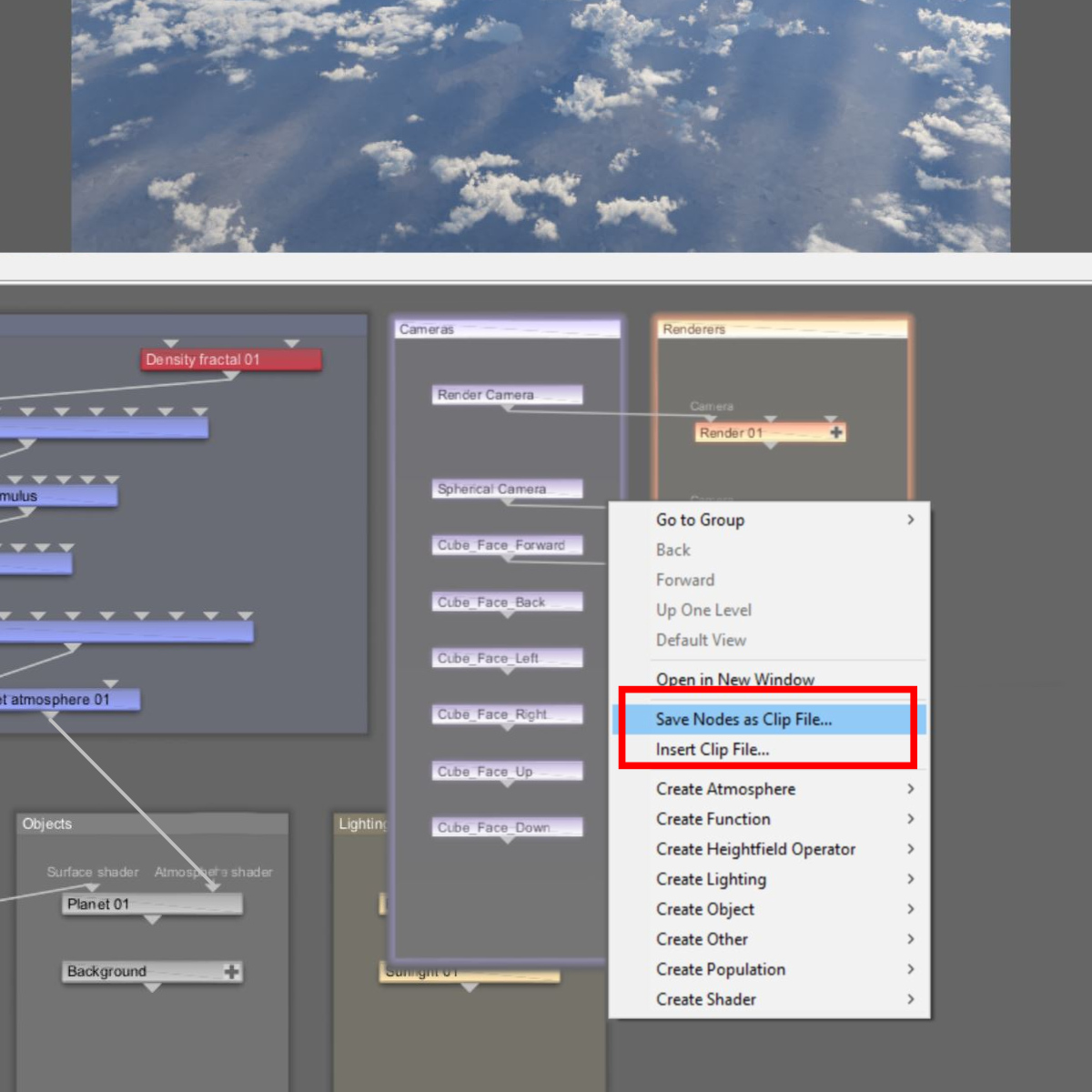
Once you’ve completed setting up the six cubemap cameras and the render node, you can save the setup as a Terragen Clip file. This allows you to easily load the setup in other Terragen projects. In the Node Network window, simply select the nodes you want to include in the clip file, then right click and choose “Save as clip file”. Likewise, you can select “Insert Clip File…” to import a saved clip file into your project.
For more information about cubemap setups in Terragen be sure to check out the VR Challenge threads on the Planetside Software Forums here.
RPC Approach
Now that we’ve covered all the steps needed to create a cubemap setup, let’s look at a method to automate the process as much as possible. By using Terragen’s built-in Remote Procedure Call (RPC) feature we can run a Python script to automatically add the camera and render nodes to the project, and set most of their parameter values as well.
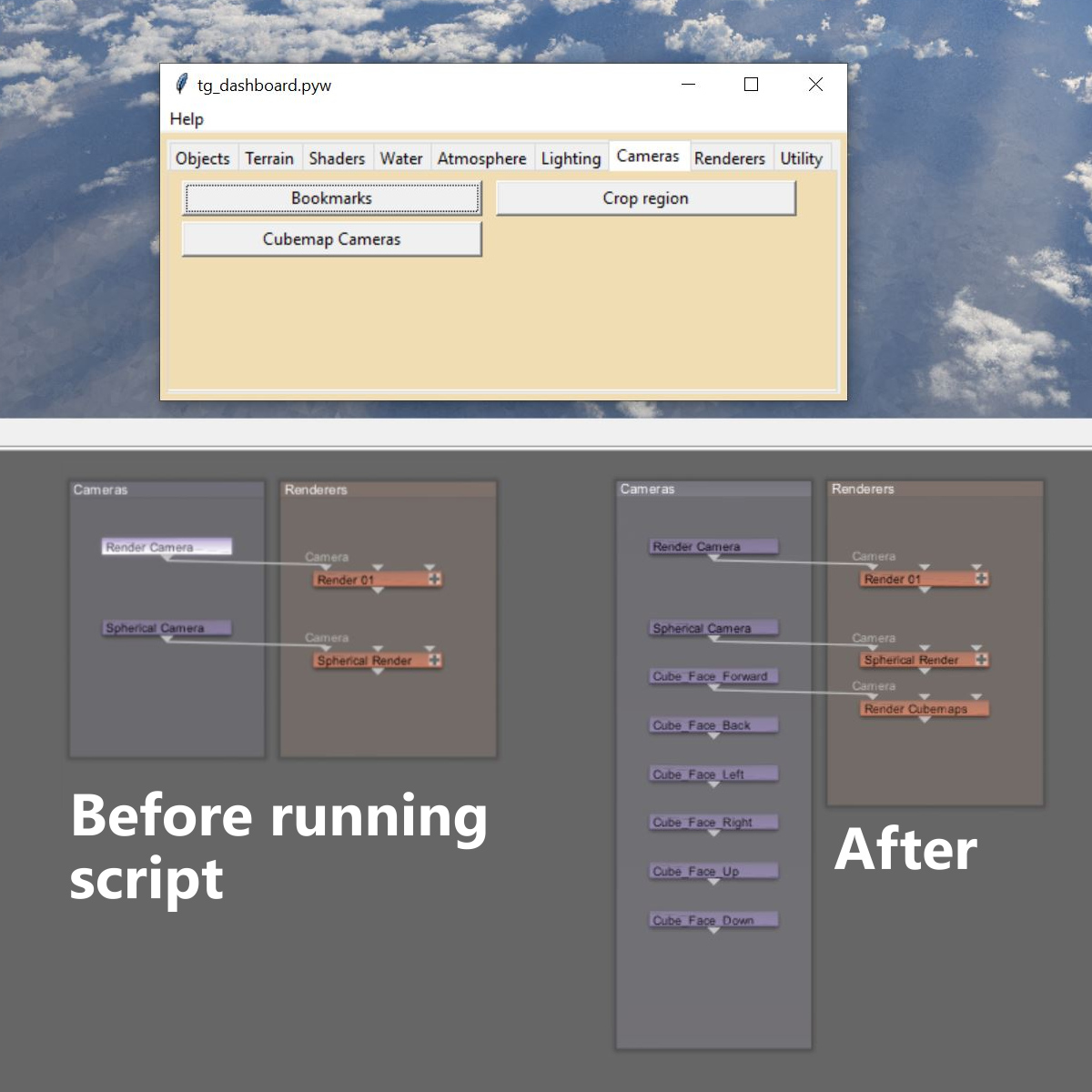
The “Cubemap Cameras” script is included in a suite of Terragen related scripts called the Redmaw TG Toolkit. Instructions to download and install the toolkit may be found in the Planetside Software Forums File Sharing section or by clicking here.
Once you’ve installed the toolkit, you’ll find a button for the Cubemap Cameras script under the Cameras tab. Start by selecting your source camera node in the Node Network of the Terragen project and then clicking the Cubemap Cameras button. It’s that simple! All six cameras and the render node will be automatically added to your project.
Note, using the RPC approach, you will still have to set the render node’s parameters, such as its Output image file and where to read the GI Cache file from.
Rendering the Cubemap Images
Regardless of which method you used to setup the cubemap camera and render nodes, now it’s just a matter of rendering each cubemap image. In the Node Network window connect the output from one of the cubemap cameras to the Camera Input of the render node, then click on the “Render to disk” button. When the render is complete, repeat the process for the next cubemap camera. Since we’ve included the camera name as part of the output file name in this example, nothing else is need.
Stitch the Cubemaps Together
The last step is to assemble the six cubemap images into one image texture. For this you can use the paint program or compositing package of your choice, or use the “Cubemap Image Stitcher” script included in the toolkit.
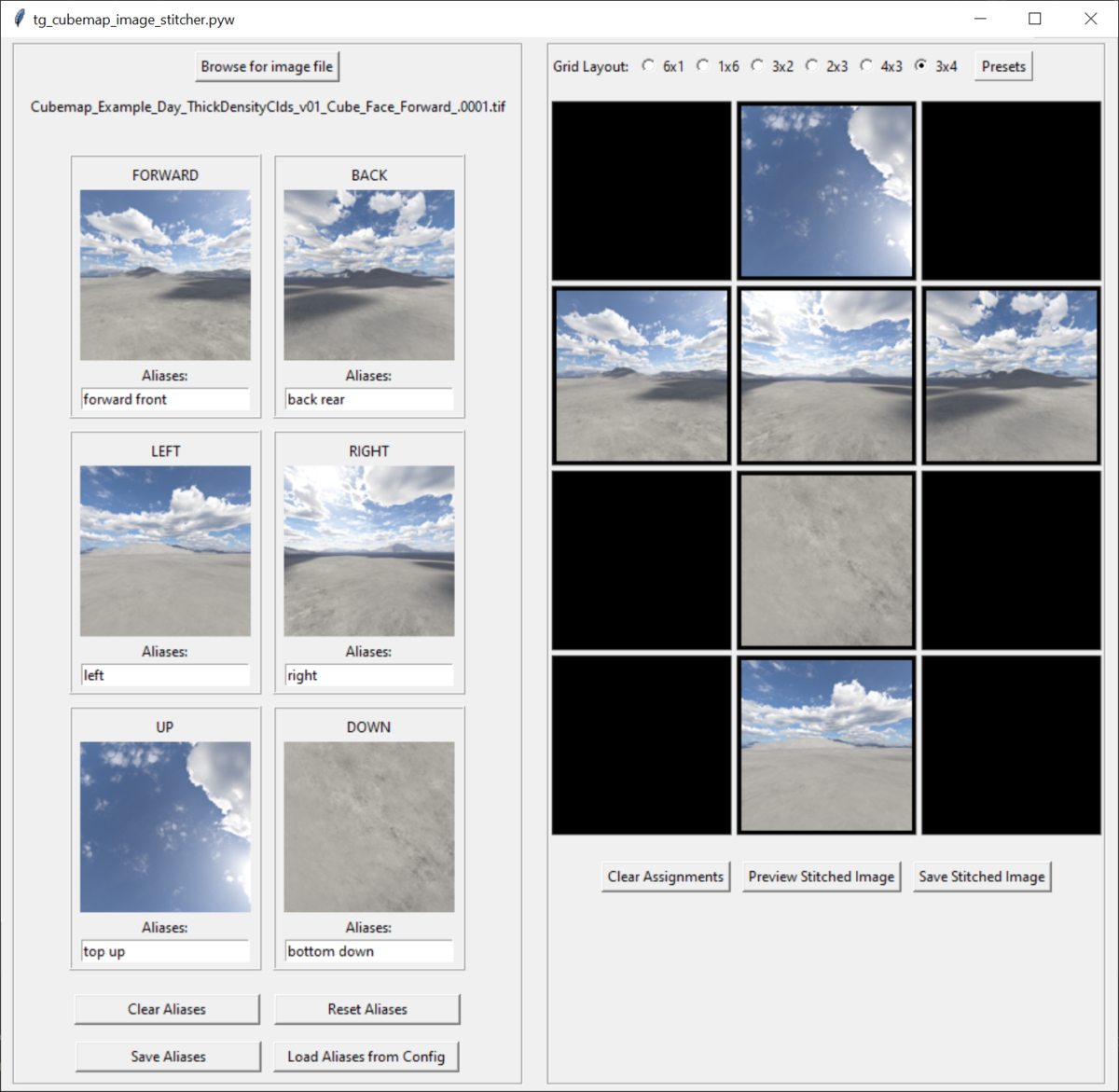
- Click the Browse for image file button and navigate to the folder containing the rendered cubemap images.
- Select one of the cubemap images in the sequence. It doesn’t matter which one.
- The script automatically assigns the first cubemap image in the sequence that matches the text in the Aliases field. Common aliases are provided by default. You can append to or overwrite these search patterns.
- Select the Grid Layout you want to use, then click on a thumbnail image to highlight it. Assign the selected image to the grid by clicking in an empty grid cell. Or, click the Presets button to select from common layouts.
- Click the Preview Stitched Image button to see a preview of the stitched image.
- Click the Save Stitched Image button to save the stitched image to disk.
- For more information about the Cubemap Image Stitch script see its documentation in the toolkit.
In Closing
Don’t forget to download the Redmaw TG Toolkit ZIP file in order to access the Cubemap Cameras and Cubemap Image Stitcher scripts, along with lots of other goodies!
You’ll find them here: https://github.com/RedMawVFX/redmaw-tg-toolkit.git
For more information about creating and using cubemaps, be sure to head over to the Planetside Software forums and seach its database. Of special interest are the images submitted for the VR Challenge, and the 360-degree cube camera setup thread. The forums contain an incredible amount of user knowledge on all sorts of topics!