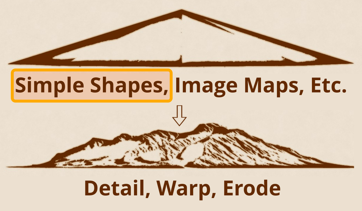
In this series of posts, we’ll explore different techniques to create art-directable terrains in Terragen.
Starting with a basic form, we’ll modify its shape, then distort it with warp shaders. To achieve realistic results, we’ll run erosion simulations and add final details as needed. At any time during this process we’ll be able to re-position and re-scale the terrain features.
Part 1: Simple Shape Shaders
The Simple Shape shader is an extremely powerful and useful tool in Terragen. It can be used to create a variety of shapes, and outputs both colour and displacement data. For this reason, it is often used for creating and manipulating forms, textures, and masks. Whether designing a terrain for a single image or animated sequence, the basic low resolution forms created by vertically displacing a Simple Shape shader allow you to easily move them about in your project and duplicate them as needed in order to block out the terrain.
Simple Shape shaders can be used to quickly compose terrain features for your shot or still image.
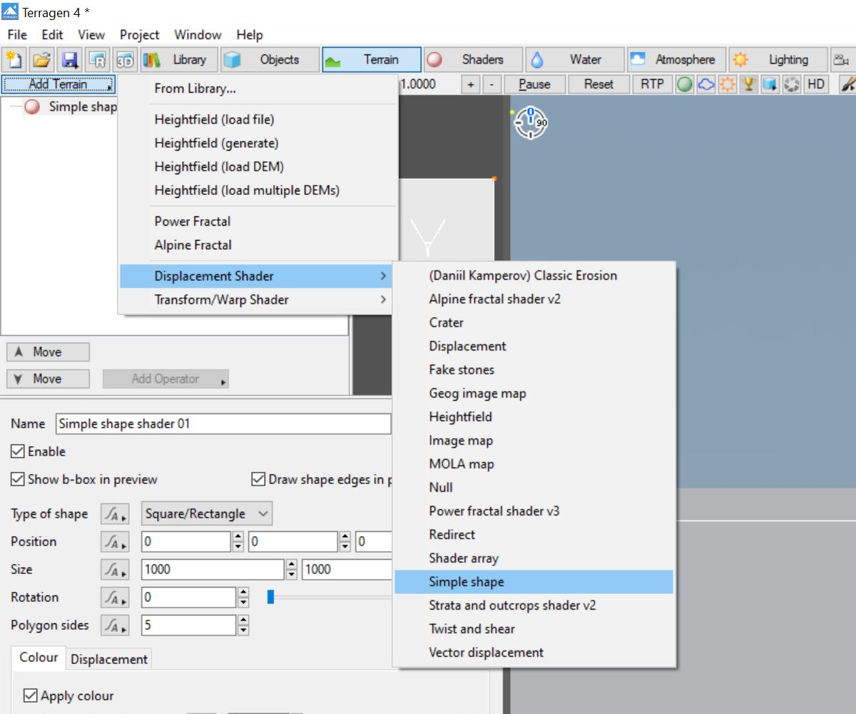
To add a Simple Shape shader to your project, click on the Terrain button in the top toolbar, then the Add Terrain button in the Node List, and select the Displacement option and Simple shape from the drop down menus.
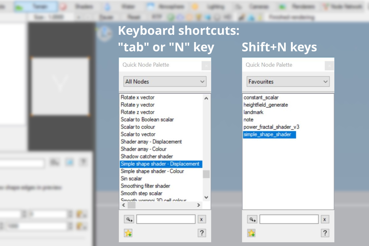
Pro-tip: You can quickly add a Simple Shape shader to your project via the Quick Node Palette feature. When the program’s focus is on the Node Network view, pressing the tab key or “N” key will bring up the Quick Node Palette. You can immediately start typing the name of the node you’re looking for, and the node list will automatically find the closest matching node name. Alternatively, pressing Shift+N will bring up the Quick Node Palette with the nodes you’ve added to your favourites list.
The Quick Node Palette feature displaying “All Nodes” on the left, and your “Favourites” on the right.
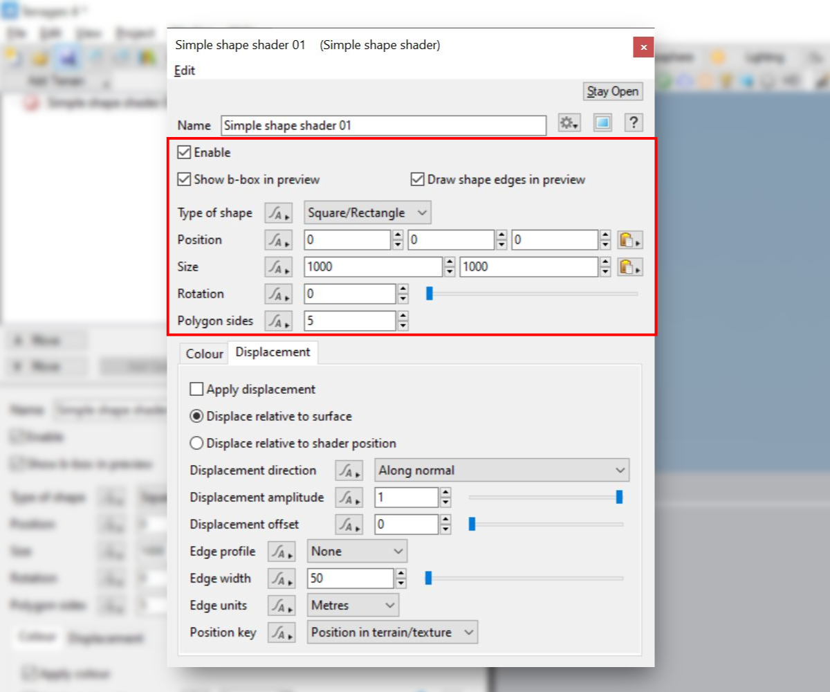
The top section of the Simple Shape shader’s node properties allow you to control its view properties, shape, position, rotation and size. You set its colour and displacement values with the parameters found under the Colour and Displacement tabs respectively.
But what if you want more control over the topography in your terrain than the parameters of the Simple Shape shader seem to allow? Let’s look at some of the tools in Terragen that allow you to modify the basic shape created by a displaced Simple Shape shader.
Defining a Basic Shape with the Simple Shape Shader
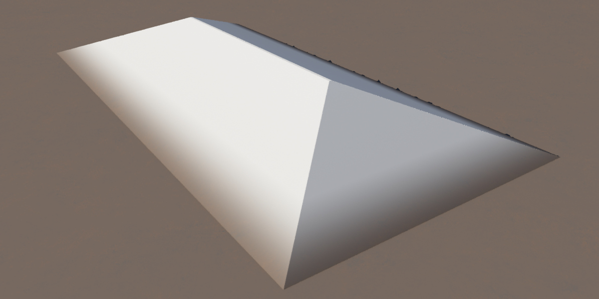
For our first example, let’s create a mountain range centered around the origin of the project. We’ll create a long rectangle shape by selecting the “Square/Rectangle” option from the Type of Shape list, and setting the Size parameter values to something like “5,000” metres wide by “10,000” metres long.
To raise the mountain range shape above the planet surface, first enable displacement by checking the Apply displacement checkbox under the Displacement tab, then increasing the Displacement Amplitude value. The value is expressed in metres. For this example, we’ve set the parameter to a value of “1,000” metres.
We can define a ridgeline along the top of the mountains, based on actual measurements in meters, or as a percentage of the shape. For this example, we’ll give the ridgeline a small thickness based on a percentage of its overall shape. Change the Edge Profile to “Bevel“, the Edge Units to “Percent“, and enter an Edge Width value of “99”. Based on the shape settings above, this will create a ridgeline approximately 50 meters wide by 5,000 meters long.
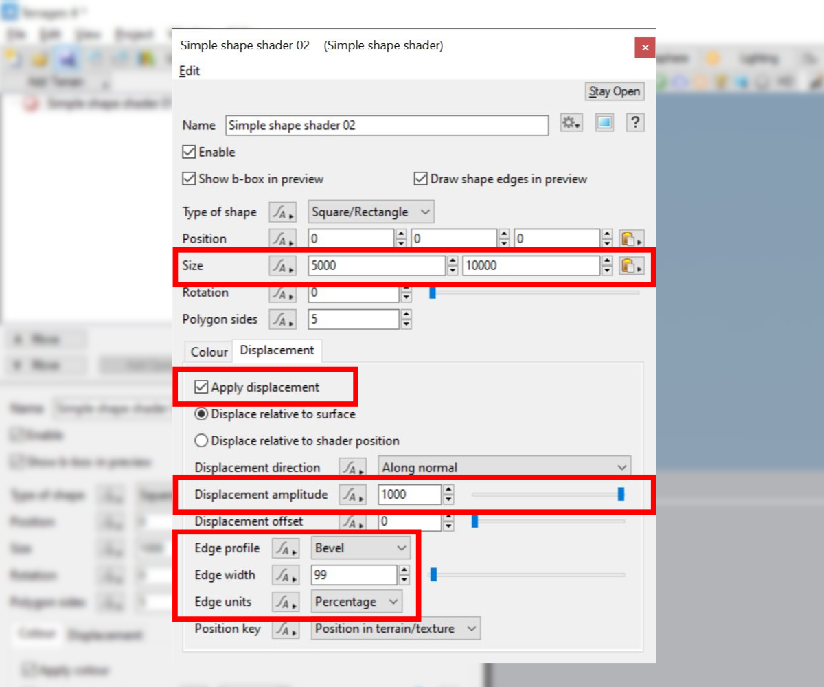
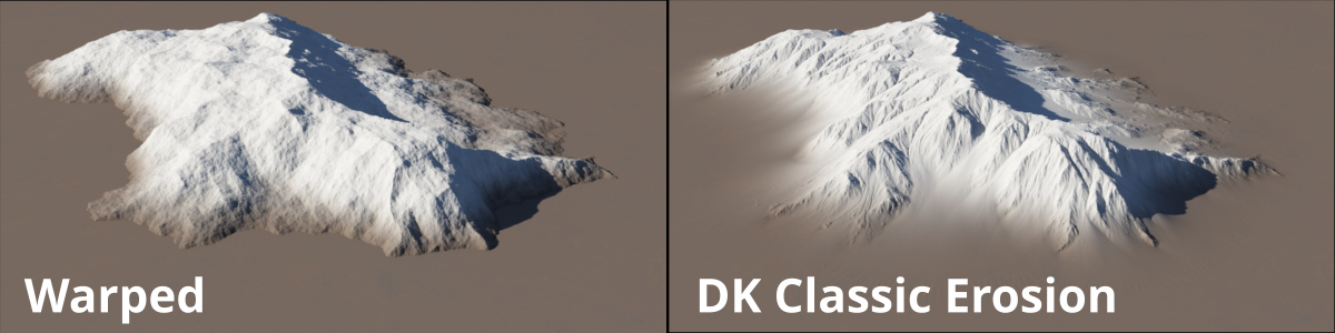
Here’s a “sneak peak” of the displaced Simple Shape shader above, after it has been warped and eroded. We’ll cover these two topics in greater detail the Detail, Warp, and Erode blog post.
Exaggerating Slopes with the Twist and Shear Shader
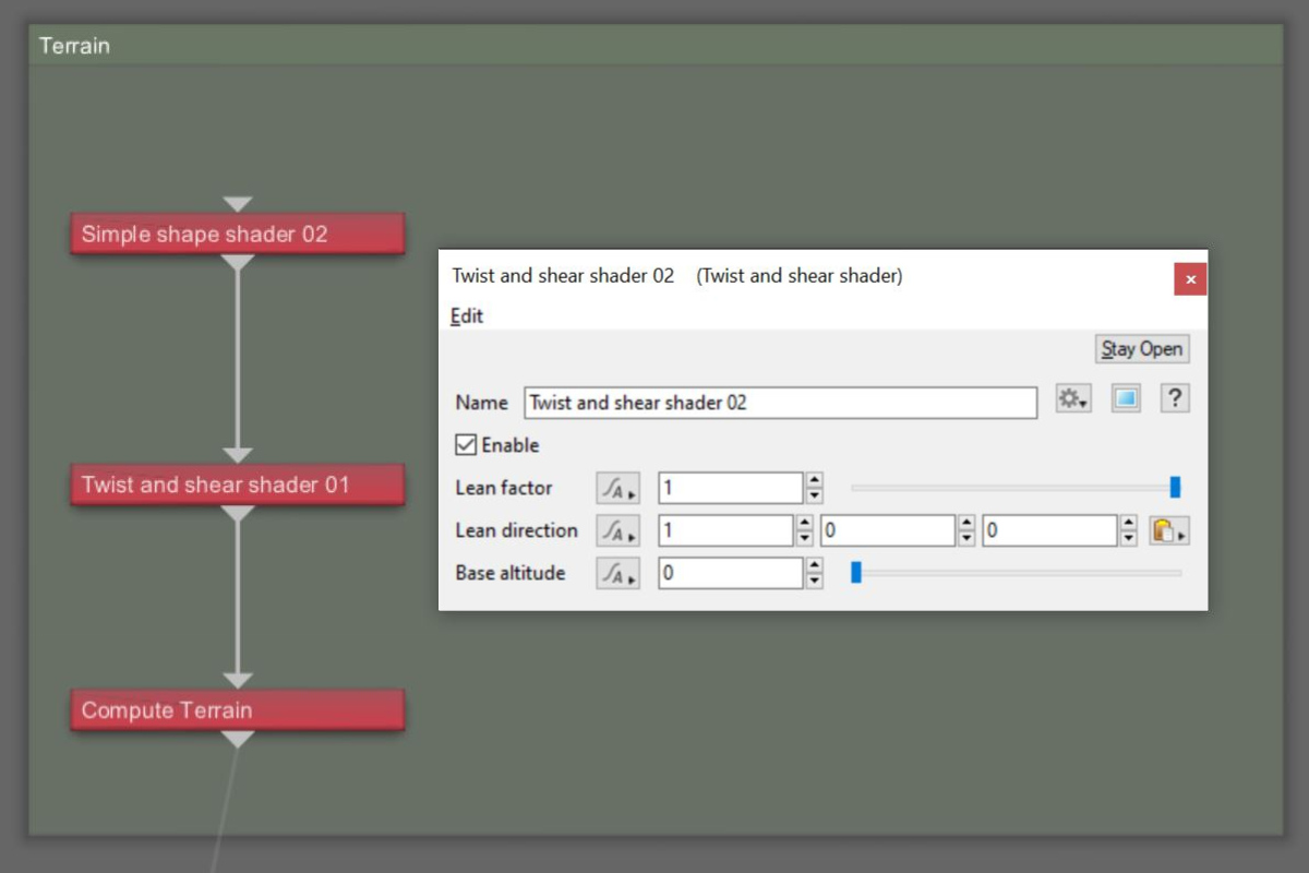
In the image of the displaced Simple Shape shader above, notice how the ridgeline is centered within the shape. We want a way to shift it to the left or right, and forward or backward, in order to give us control over its position and the initial slope of the mountain range. We can do this with the Twist and Shear shader. Repeat the steps used above to add a Simple Shape shader to the project, but this time select the Twist and Shear Shader.
After adding the Twist and Shear shader to the project, it will show up beneath the Simple Shape shader in the Node Network view.
By default, the shader’s Lean direction is set to “1” in the X axis and “0” in the “Y” and “Z” axis. These settings will allow us to shift the ridgeline to the left and right based on the value we enter in the Lean Factor setting. You can shift the ridgeline forward and backwards by entering a value of “1” in the “Z” axis, and even up and down by entering a value of “1” in the “Y” axis.
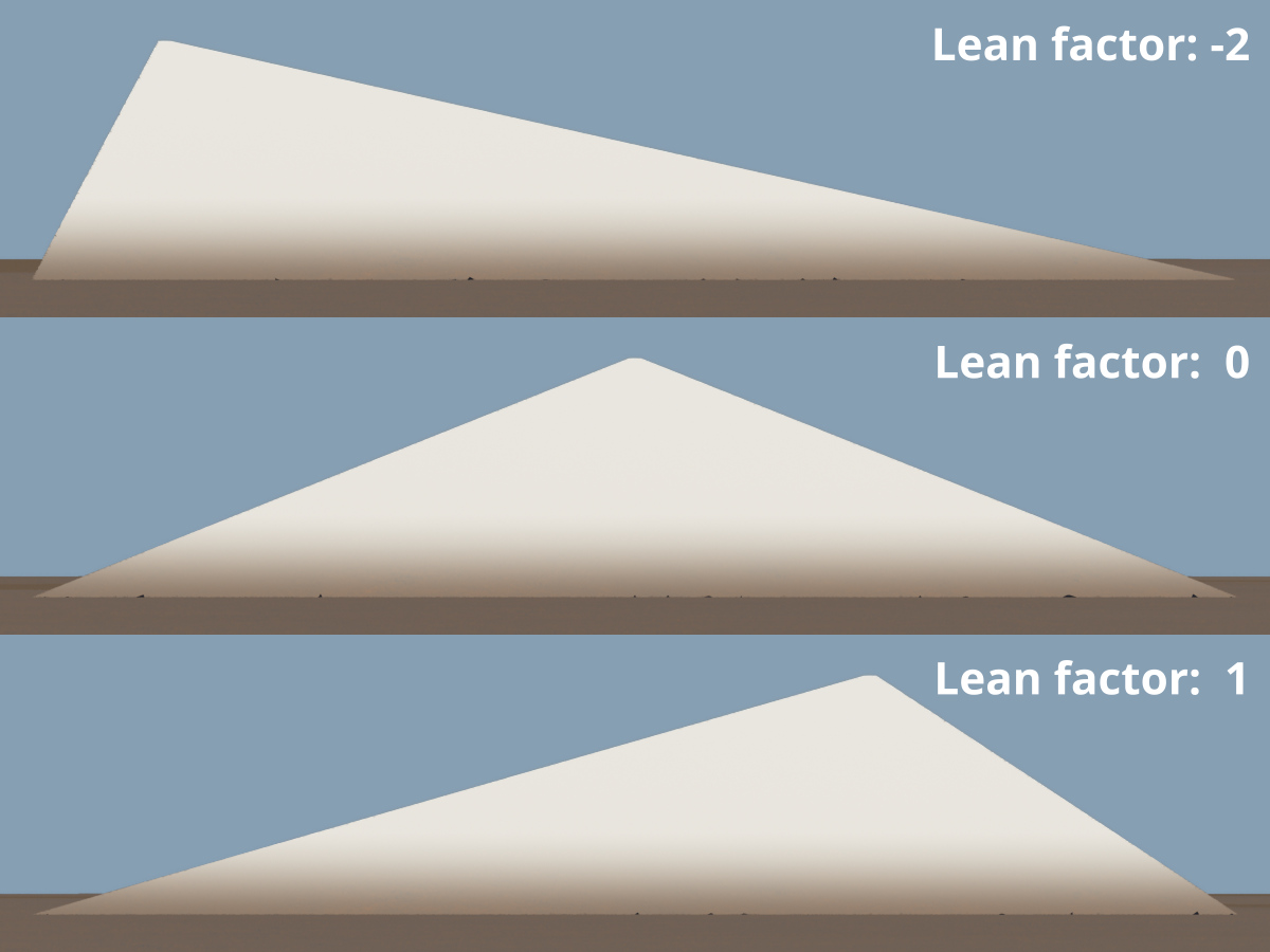
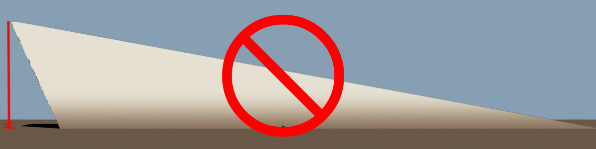
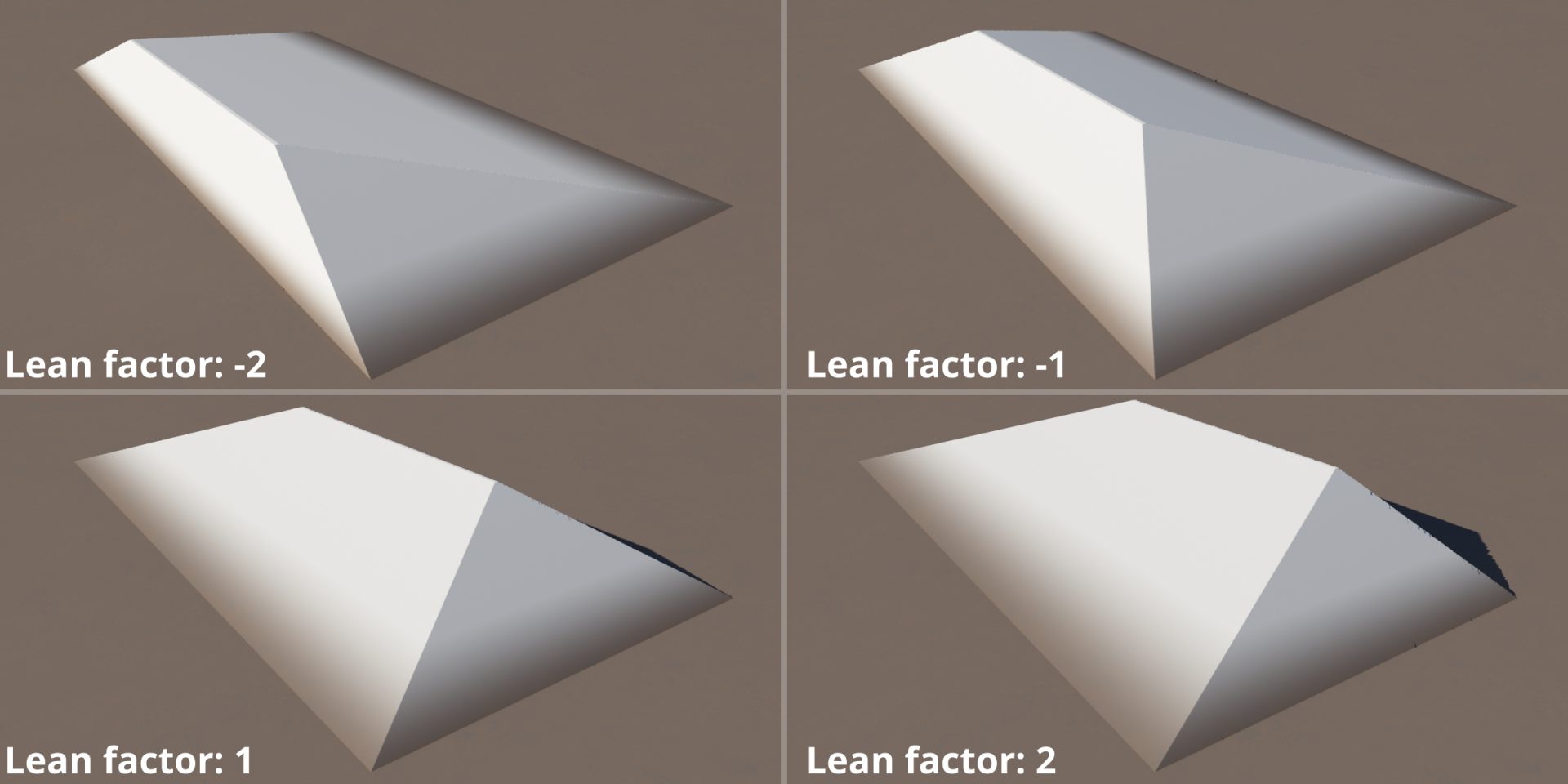
As we shift the ridgeline, notice how the slope on one side of the mountain range lessens, while the other side becomes steeper. Experiment with the Lean direction and Lean factor settings to come up with something pleasing, but avoid extreme values that create overhanging features. Terrain features that overhang are not desirable at this point in the process because we’ll shortly be generating a heightfield of our shape, and a heightfield can not account for undercut features.
Avoid Lean factor values that create overhanging terrain at this point in the process.
Here are some examples of what the shape might look like after applying the Twist and Shear shader.
Adding Terraces with the Strata and Outcrops Shader
The Strata and Outcrops shader is often used to add fine layers of detail to the final terrain, but it can also be used to reshape the basic form created by the Simple Shape shader.
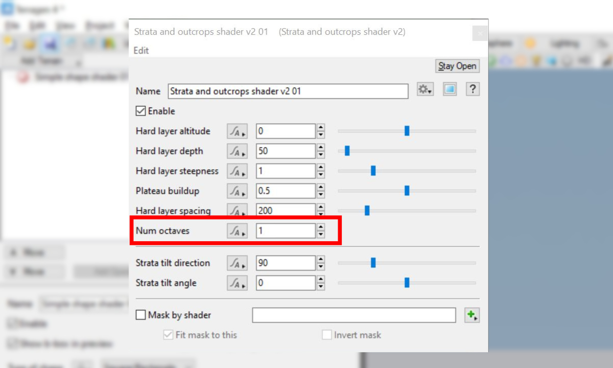
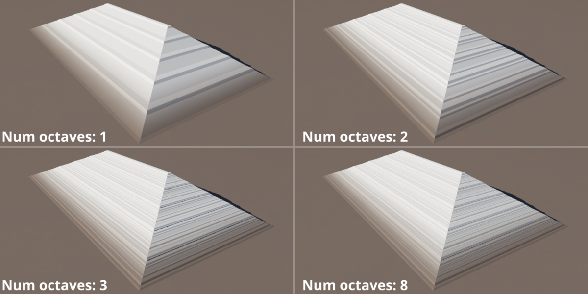
Add the shader to the project in exactly the same way as we did with the previous two shaders. Then, reduce the Num Octaves value to “1”. This will clearly show the strata along the mountain range.
As the Num Octaves value increases, additional levels of strata are added to the terrain. We want to keep this value low at this stage in the process.
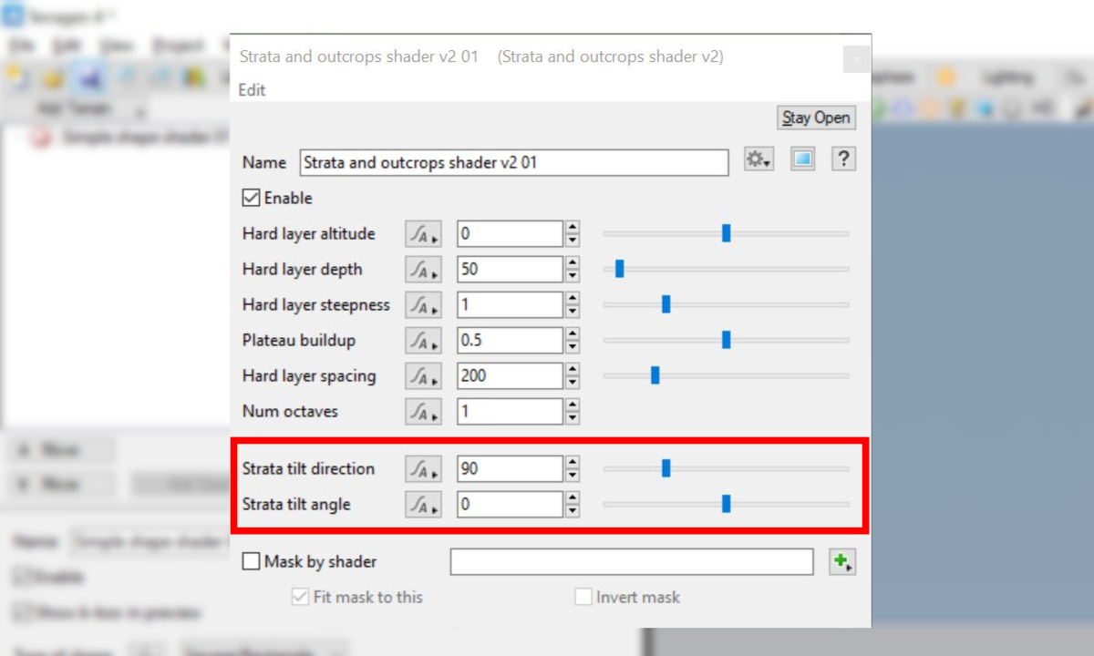
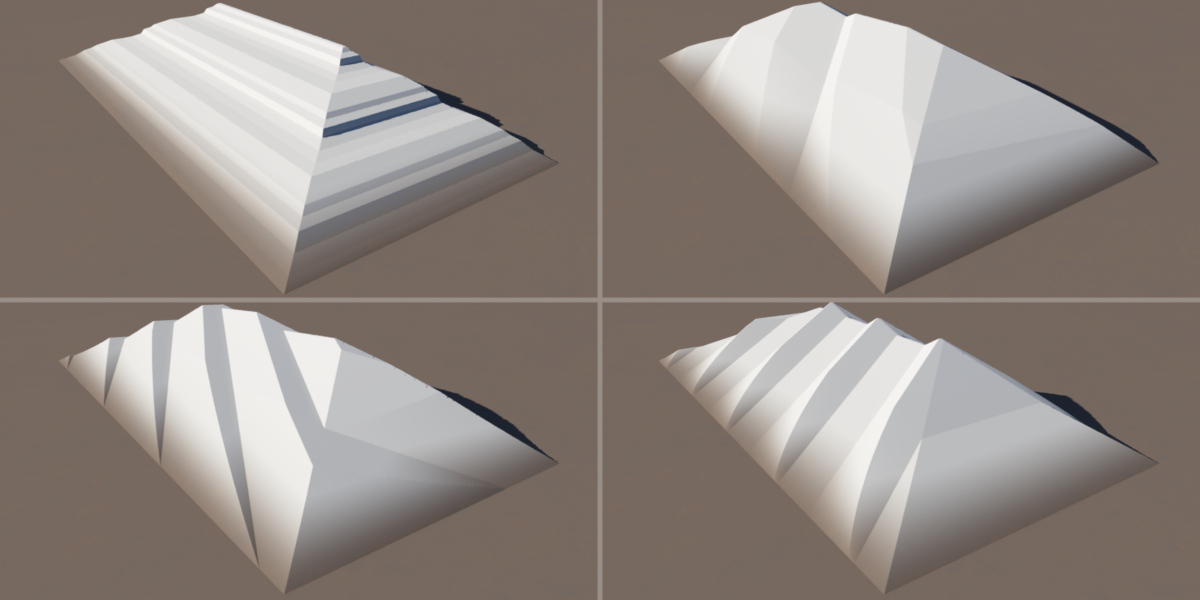
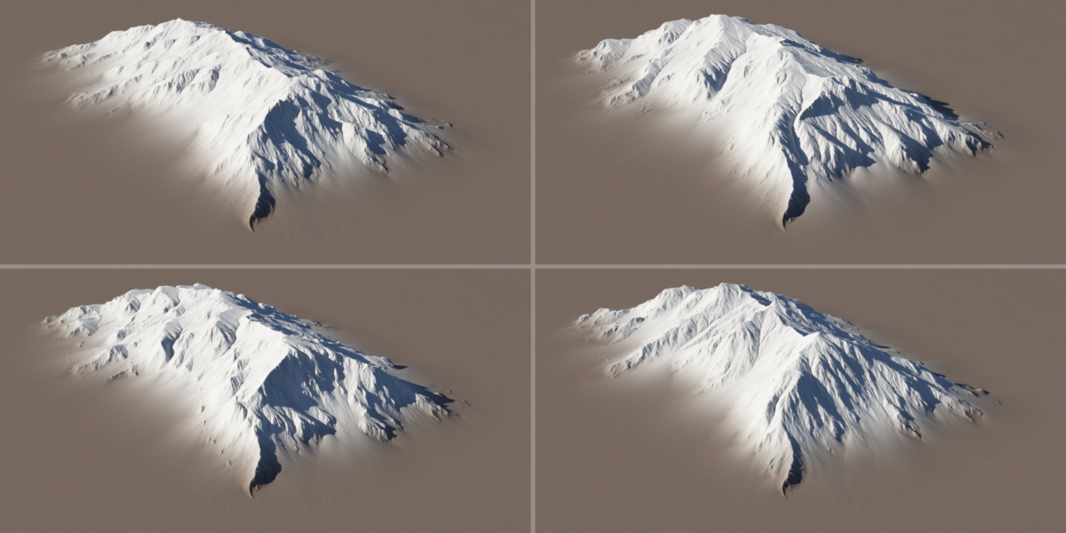
By adjusting the parameters of the shader, such as the Strata Tilt Direction and Strata Tilt Angle you can completely change the shape we’ve created so far.
Here are some examples of how quickly the shader can completely change the base shape. As we “sculpt” the basic shape over the next few steps, keep in mind that the goal is not to create the final details of the terrain yet. Rather, we’re working in broad strokes that allow us to quickly manipulate the overall form’s shape.
Here’s another “sneak peak” of the base shapes above, after running an erosion simulation on them.
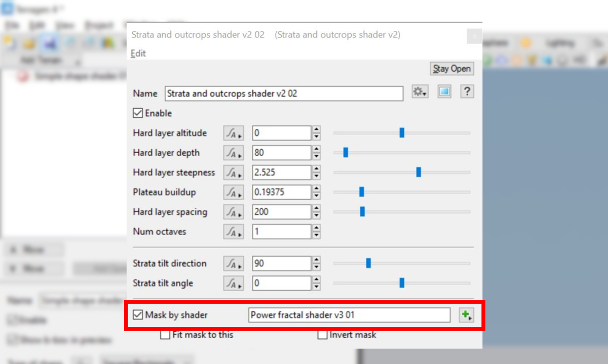
You can further control where the shader is applied to the form, by assigning a mask to the shader’s Mask by shader input.
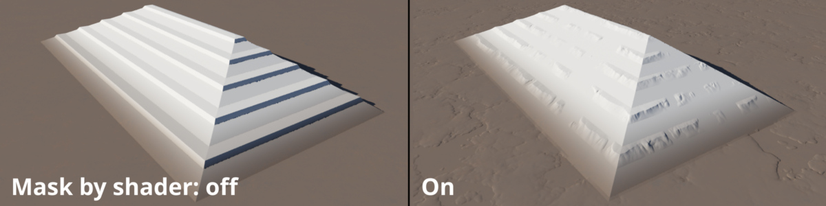
The example below illustrates how a shader applied as a mask can constrain where the effect of the Strata and Outcrops shader takes place on the basic form.
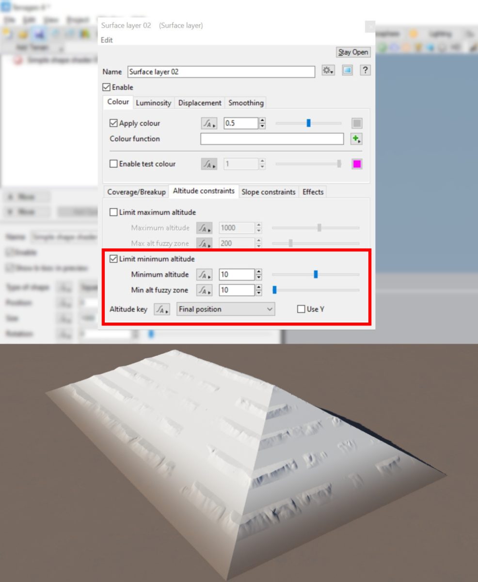
Pro-tip: The Surface Layer shader is a multi-purpose shader that can constrain child layers by its built-in masking functions for elevation and slope. In the example image above, the displacement extends beyond the mountain shape to the surrounding planet surface. By adding a Surface Layer shader to the project, and making the Strata and Outcrops shader a child of it, you can limit the strata displacement to the mountain shape. This is in addition to any shaders applied directly to the Strata and Outcrops shader itself.
Varying the Elevation with the Fake Stones Shader
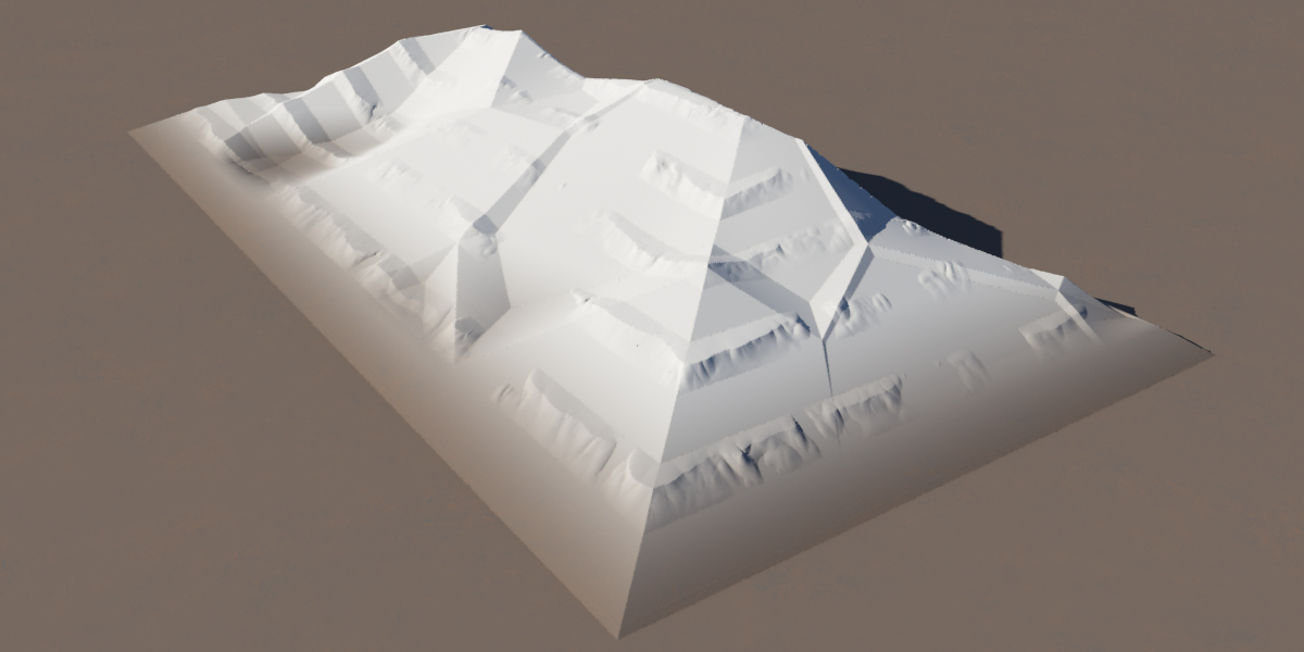
Any shader in Terragen that can output displacement data may be used to vary the elevation of our mountain range. For this demonstration, we’ll use a Fake Stones shader to break up the straight ridgeline at the top of the mountain form. Like the Strata and Outcrops shader, this shader is often used for adding final details to a terrain, but it can also be used to re-shape our basic form.
A Fake Stones shader used to vary the elevation of the ridgeline in our example mountain shape.
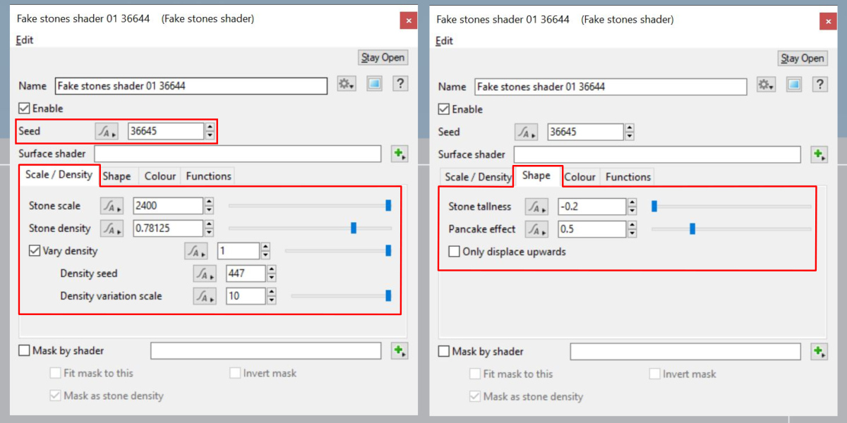
Pro-tip: Displacements and warping modifies the texture coordinates and normals of a surface. At times it may be necessary to recalculate these items in order for a downstream node to work predictably. Terragen provides the Compute Terrain, Tex Coords from XYZ, and Compute Normals nodes to address these issues. Because we’ve made a number of displacements to the original planet surface it’s a good idea to recalculate the texture coordinates before adding the Fake Stones shader.
By applying a negative value to the Stone Tallness setting under the Shape tab, you can preserve the overall height of the mountain range while varying the ridgeline elevation. This will create peaks and valleys within the basic shape. The size of the peaks and valleys can be controlled via the Stone Scale setting under the Scale/Density tab, and the frequency of peaks and valleys is controlled via the Stone Density setting. Changing the Seed Value can yield “variations on a theme” for the current settings.
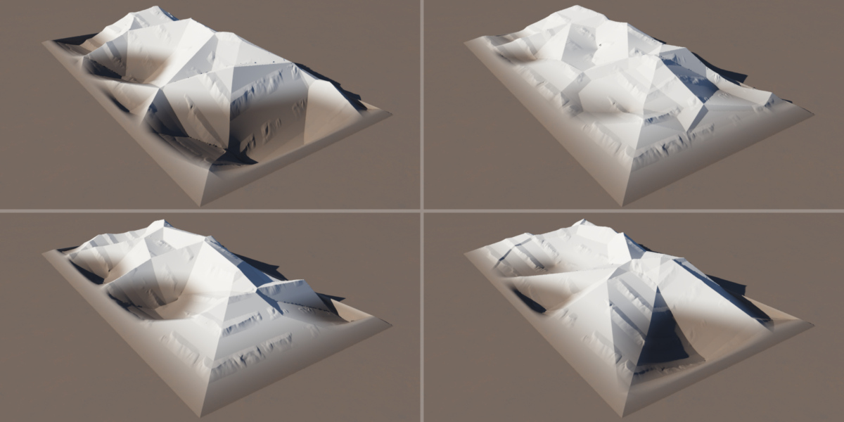
Below are some examples of how the Fake Stones shader can reshape the basic mountain range form.
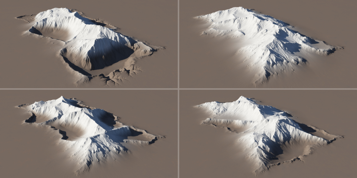
One last “sneak peak” of the displaced and modified shapes above, after an erosion simulation has been run on them.
Beyond One Simple Shape Shader
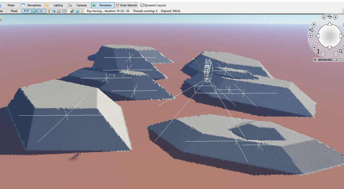
The examples above have have focused on modifying just one Simple Shape shader. Following these techniques, you can create individual “set pieces” for your Terragen projects. Having a collection of these assets can be a great starting point for building more complex terrains.
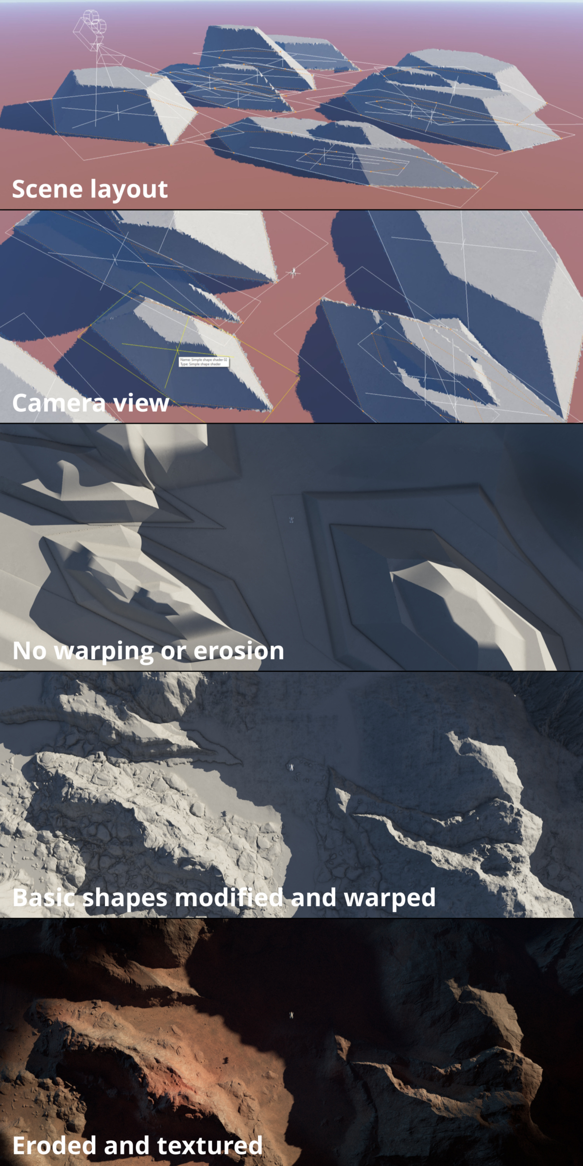
To illustrate how simple shapes can be used to create a more complex terrain, we created an animated shot in which the terrain consists of nothing more than ten Simple Shape shaders. Their basic shapes have been modified with the techniques described above, then warped and eroded using techniques described in the “Detail, Warp, Erode” blog post.
Overlapping And Combining Simple Shape Shaders
One last technique not to be overlooked is that Simple Shape shaders can overlap or be stacked on top of each other. This combination can create intriguing landscape features, especially when warped and eroded.
Try It For Yourself
Click here to download a Terragen 4 project file that includes examples and step-by-step instructions for the Simple Shape shader workflow described in this post.
Other Posts In This Series
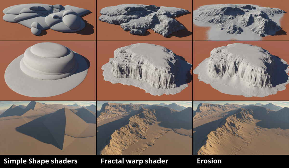
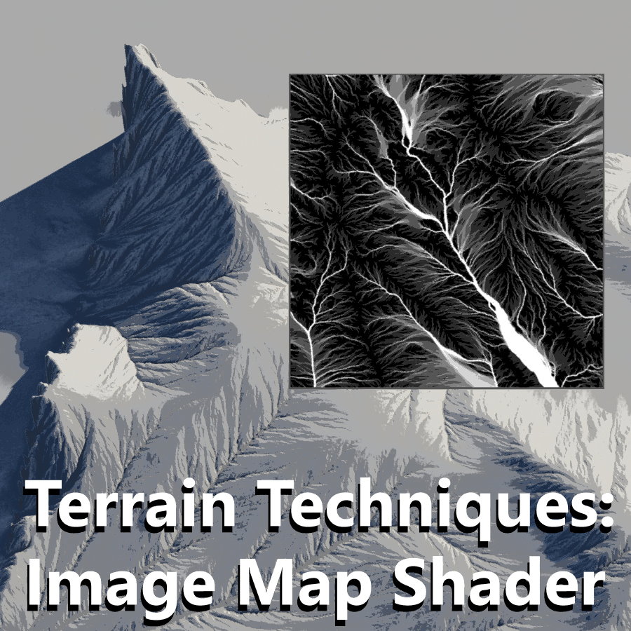
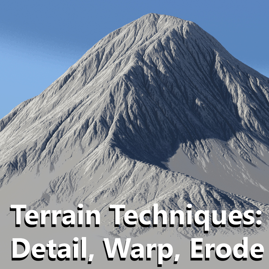
As you can see, starting with Simple Shape shaders and modifying their forms can result in complex terrains. Even as you add warping and erosion processes to the workflow, these basic shapes can still be easily adjusted. In the next posts, we’ll look at how the Image Map shader can be used in a similar manner, and how Warp shaders and Erosion operators work their “magic” to turn a basic form into a realistic terrain.
Be sure to check out these other blog posts in our Terrain Techniques series.