In this post, we’ll export terrain from Terragen as textured 3D geometry for use in other applications like Blender and Unreal Engine.
A common method of exporting terrain relies on an orthographic camera situated above the terrain and looking towards it. This type of projection tends to uniformly distribute the detail across the terrain.
In Terragen 4 Professional, you have the ability to export terrain not only from an orthographic camera but from a perspective camera as well.
When a perspective camera is used, the detail in the exported mesh is based upon how much a terrain feature occupies the camera’s field of view, in other words, how much “screen space” it takes up. This allows you to have more detail where you actually see it.
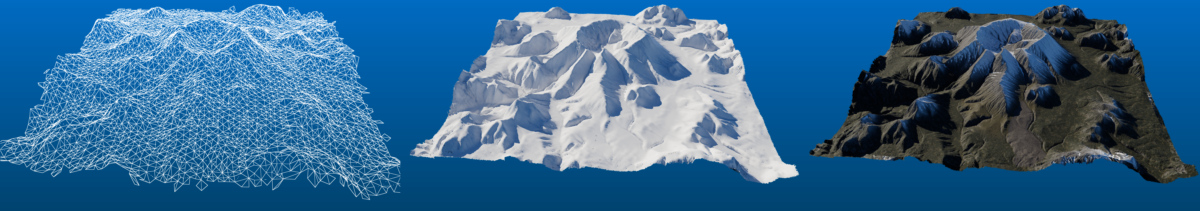
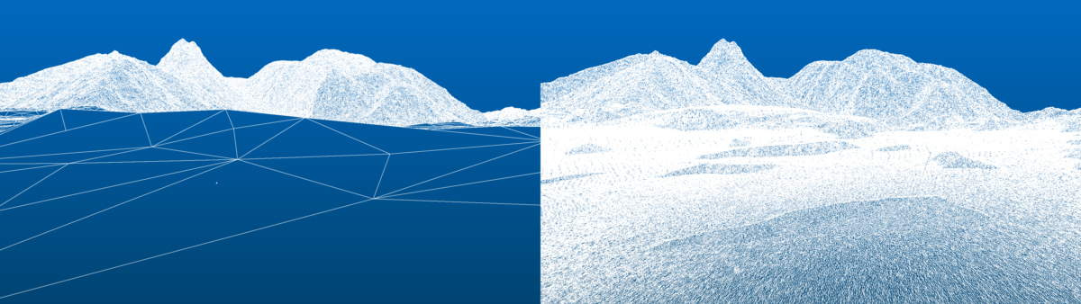
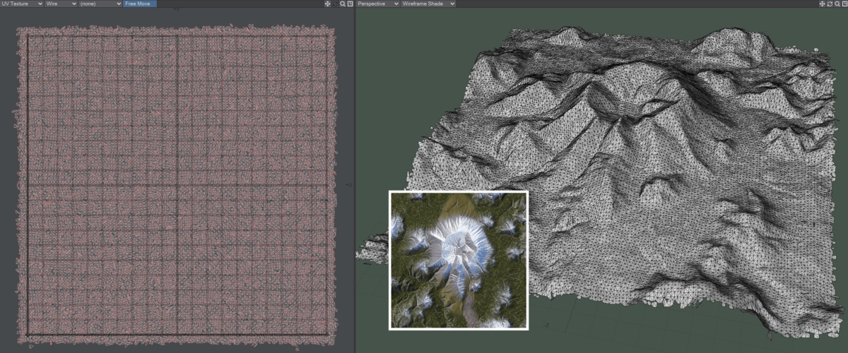
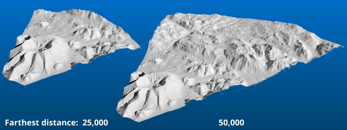
In the image below, the geometry on the right was exported from the perspective camera’s position. Note how the polygons in the foreground are small and conform to the uneven ground features. Compare this to the geometry on the left, which was exported from far above the terrain. Can you see how only a few polygons define the entire foreground area?
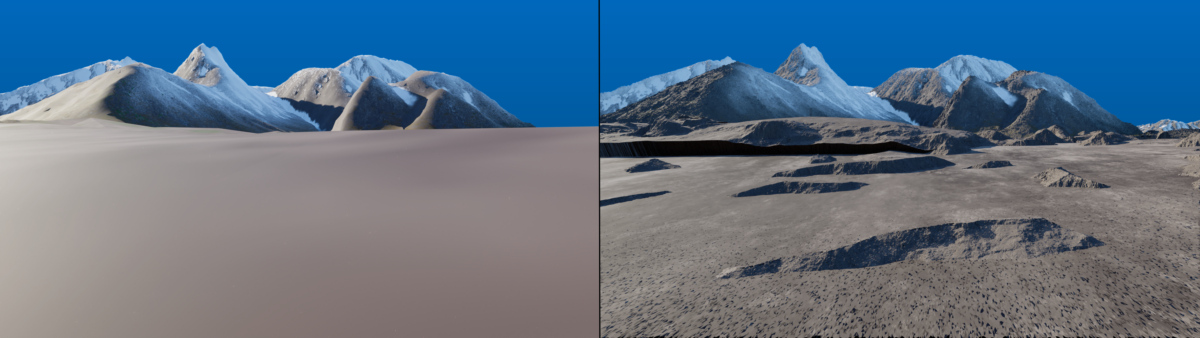
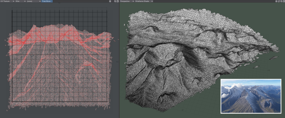
A similar situation can occur with texture maps, when viewing the textured terrain up close. In the image on the left the texture maps were exported from an orthographic camera high above the terrain. The image on the right was exported from the perspective render camera’s position. Note how the terrain textures on the left are dull and blurry, compared to the textures on the right, which are sharp and full of detail.
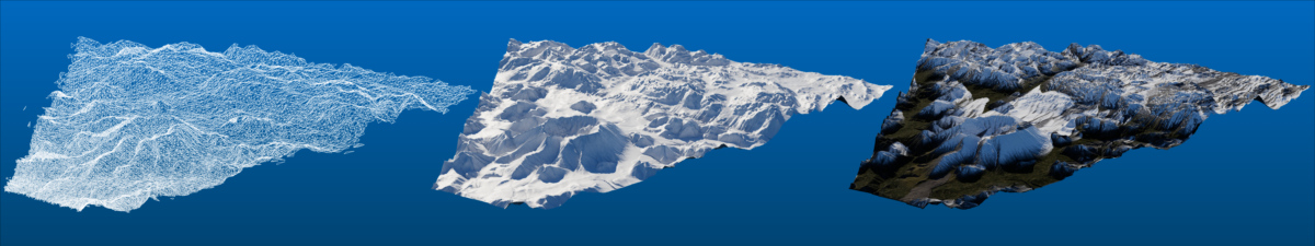
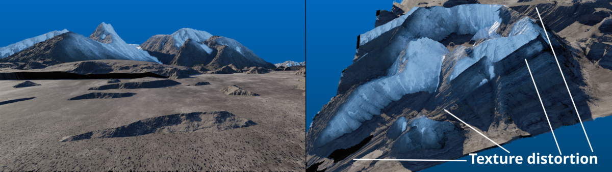
In the next image, texture maps of the terrain surface have also been exported via the perspective camera. Note on the left, how the texture maps align perfectly with the terrain geometry when viewed through the perspective camera. When viewing the same geometry and textures from a different vantage point, as on the right, you can see that the textures become distorted across the terrain.
During the render process Terragen calculates the terrain and its textures. Built into each render node are two features that allow you to save 3D objects with UV coordinates, and images which can be used for texture maps. These are the Micro Exporter and Render Layer features.
Exporting Geometry
The Micro Exporter
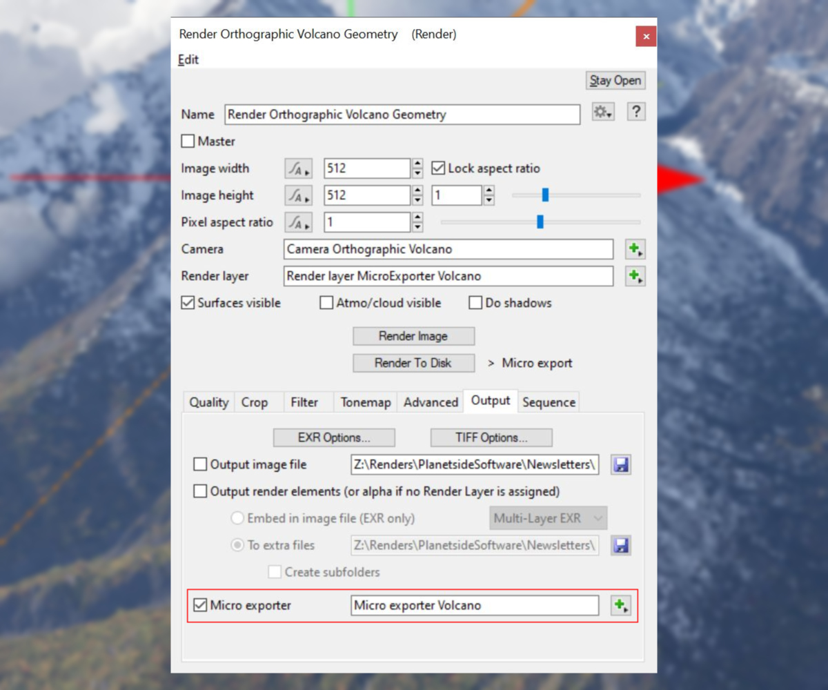
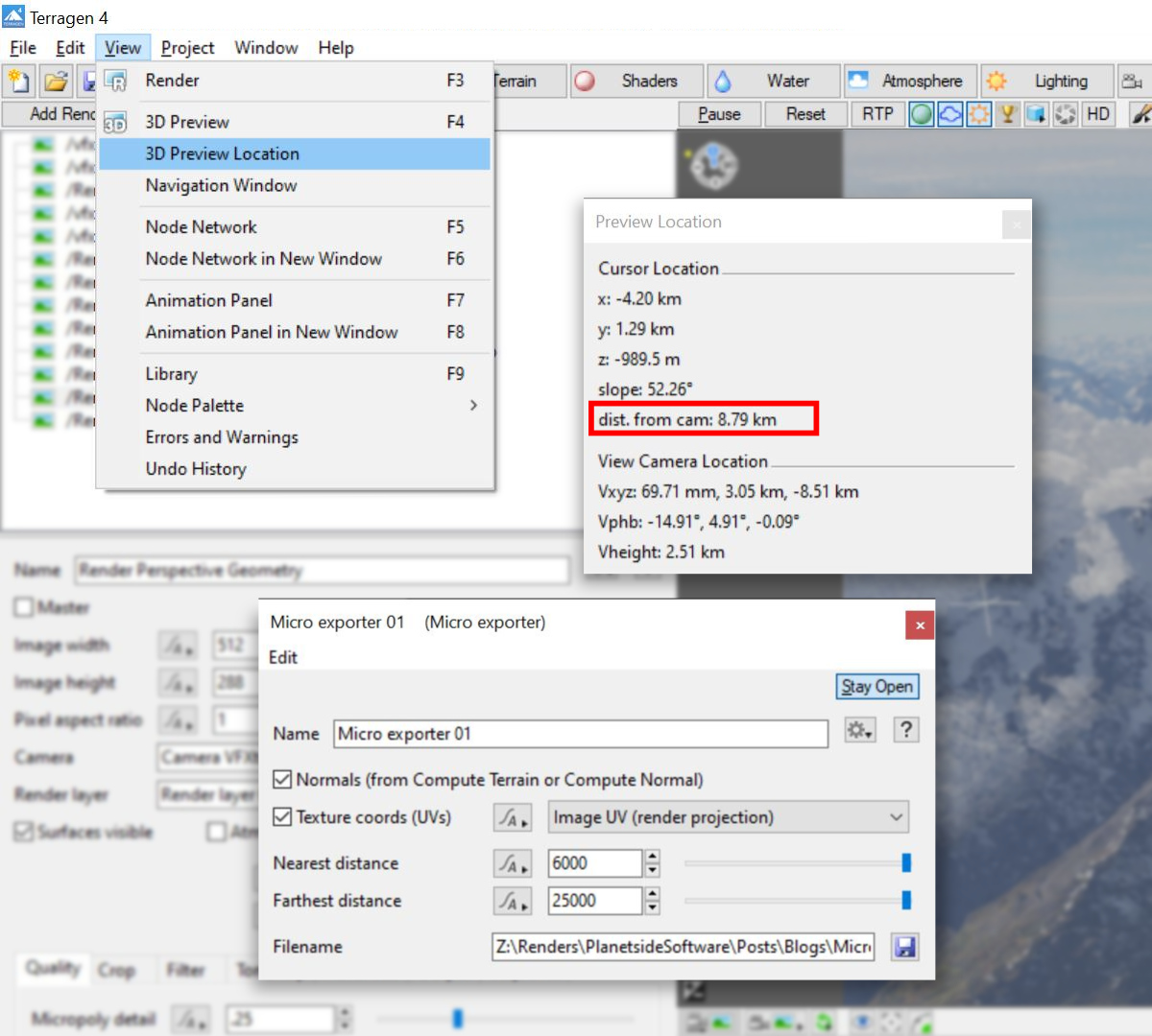
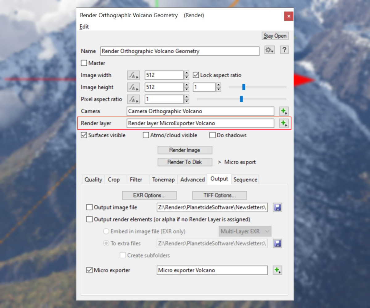
Let’s set up a renderer to be able to export geometry. You’ll find the Micro Exporter feature under the Output tab of the render node.
To create and assign a Micro Exporter node to the renderer simply click the green “+” button to the right of the parameter and select “Create new micro handler”, and then “Micro exporter”.
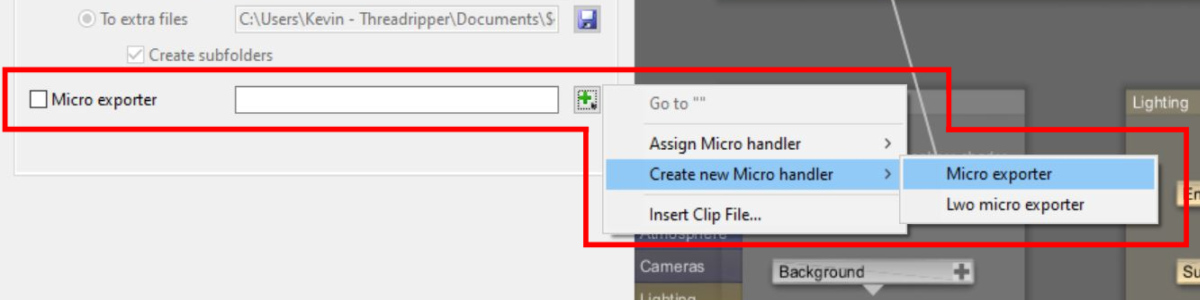
Once assigned, you can open the Micro exporter window by clicking on the green “+” button and selecting “Go to Micro Exporter”.

There are several noteworthy parameters on the Micro Exporter that affect how the 3D geometry is saved.
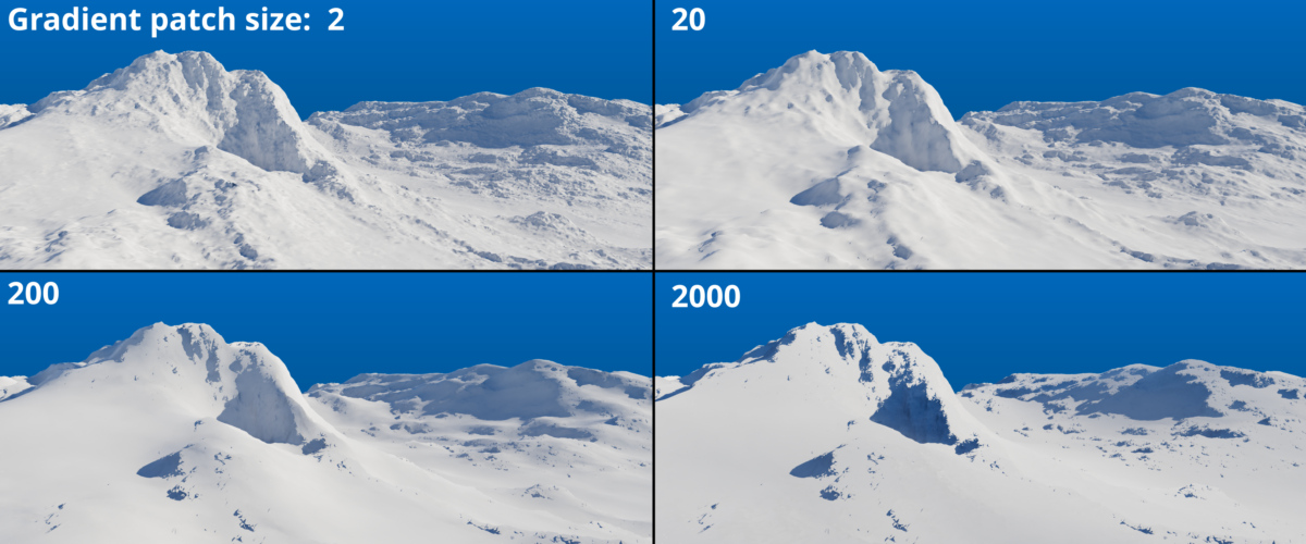
When the Normals (from Compute Terrain or Compute Normal) checkbox is checked, normal values are included in the object file exported from the Micro Exporter. When unchecked, the normal values are not included in the object file, resulting in a slightly smaller file size for the exported mesh. The terrain’s normal values are calculated by the Compute Terrain or Compute Normal nodes in the project. The Gradient patch size parameter of the Compute Terrain node can affect the perceived smoothness of the mesh.
The Texture Coords (UVs) parameter includes two options on which to base the exported UV data.

When Image UV (render Projection) is selected, the terrain is mapped into the 0 to 1 range of UV space, based on the camera’s point of view. For example, what the camera sees at its bottom left, is mapped to the UV coordinates 0,0. What it sees at its top right is mapped to the UV coordinates 1,1.
When UVW from Compute Terrain or Tex Coords is selected, 3D world space coordinates as determined by the last Compute Terrain node or Tex Coords node are saved with the exported geometry. Retaining 3D world space coordinates can be useful in certain cases. For example, if the exported OBJ or FBX geometry was imported back into Terragen and further manipulations were desired, such as additional displacements or texture modifications.
The Nearest Distance and Farthest Distance parameters allow you to export only the terrain within their limits. These values are based on the camera’s position and expressed in metres. The 3D Preview Location tool found under the View menu can be used to determine precise distances from the camera.
Be sure to set the Filename to the location you wish to export the 3D mesh to.
To access the Micro exporter online documentation click on the “?” button in the upper right of the Micro Exporter window.
Mesh Quality and Level of Detail
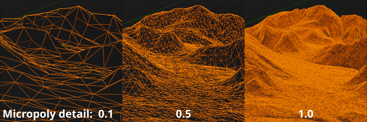
The level of detail, or quality, of the output mesh is controlled by the render node’s Image width, Image height, and Micropoly detail parameters. A mesh generated with the Image width and Image height values set to “1024” and the Micropoly detail value set to “1.0” would be practically identical to a mesh generated with the Image width and Image height vales at “2048” and the Micro poly detail value set to “0.5”, as would a mesh generated with the Image width and Image height values at “512” and the Micropoly detail value at “2.0”. By understanding this relationship, you can generate both low resolution geometry and high resolution geometry, depending on your needs.
The OBJ and FBX files produced by the Micro exporter can be quite large and their polygon count may exceed the maximum allowed by the third party applications. We recommend testing the export process using lower Micropoly detail values to begin with.
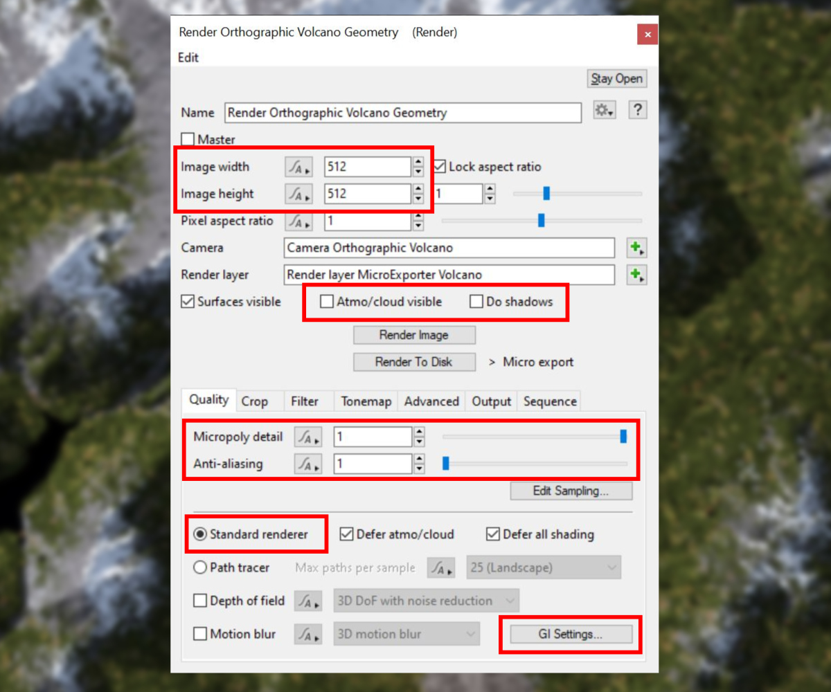
You can turn off or disable any render parameter that doesn’t directly contribute to the final mesh. This includes the Atmo/Cloud visible and Do Shadows checkboxes.
The Anti-aliasing value can be set to “1” to reduce render times.
In order to reduce render times we recommend using the Standard Renderer and not the Path Tracer.
Pro-tip: When exporting geometry, you can decrease render times by unchecking the Surfaces visible checkbox. Be aware that the Render View’s RGB display will be black, which might be confusing. However, if you view the Render View’s Alpha display, you’ll see the buckets as they are being rendered, and filled with the alpha channel value as the render thread completes its task.
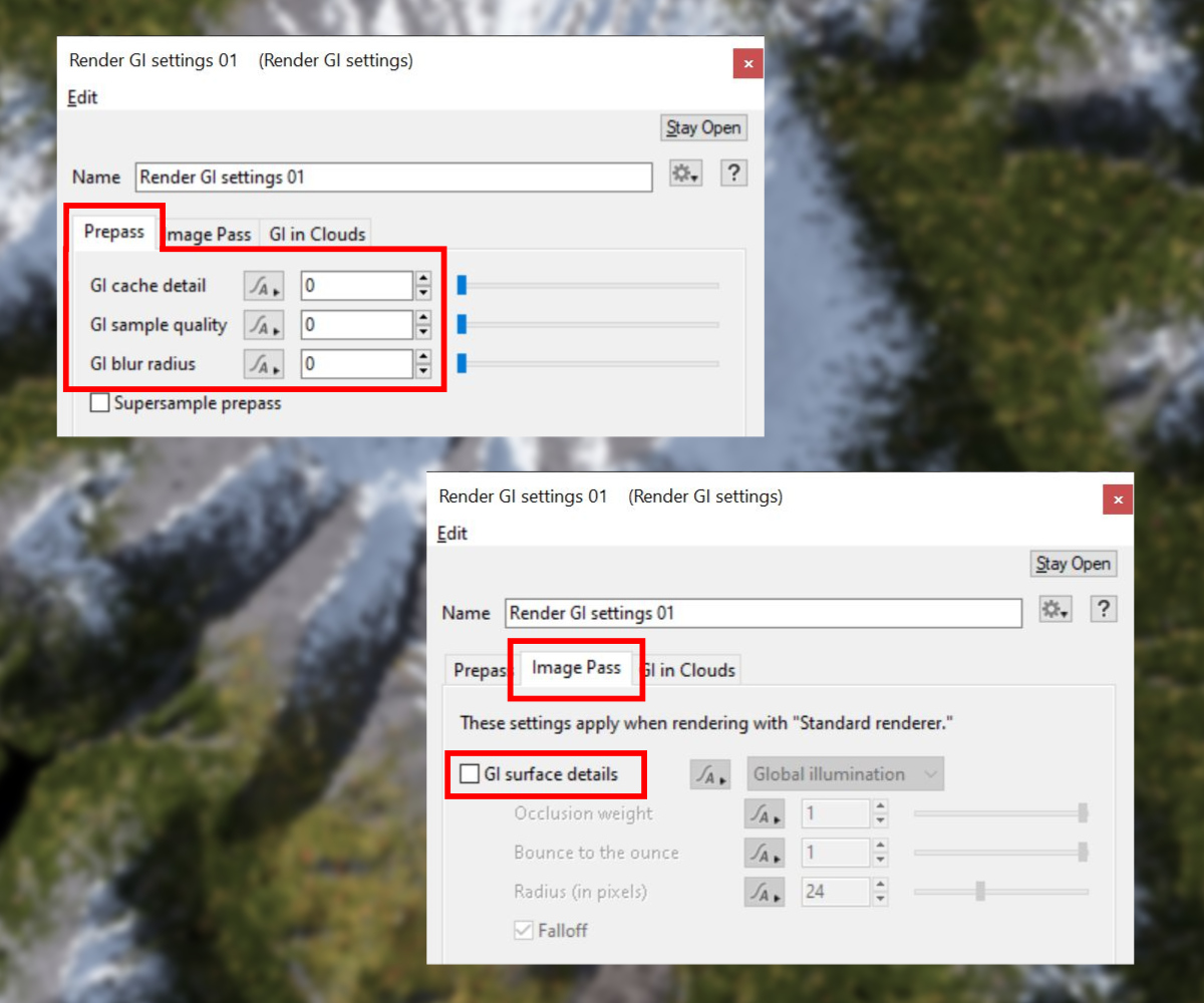
The global illumination, or GI, settings can also be disabled as lighting will not contribute to the final mesh either. Click the GI Settings button to open its window and under the Prepass tab, set the Gi cache detail, GI sample quality, and GI blur radius to “0”. On the Image Pass tab uncheck the GI surface details checkbox.
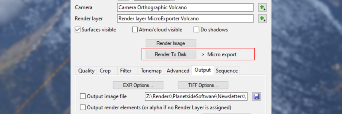
Text is displayed to the right of the Render to Disk button indicating the types of data which will be saved to disk. To start the process of rendering and exporting the terrain, simply click the button.
Exporting Textures
Now we can export images of the terrain that can be used as texture maps for the 3D mesh. While it’s possible to use one render node to save the 3D mesh and images at the same time, we recommend splitting these tasks across two render nodes. This way the render node may be optimized for each task. For example, you may wish to render the images at a higher resolution than the 3D mesh.
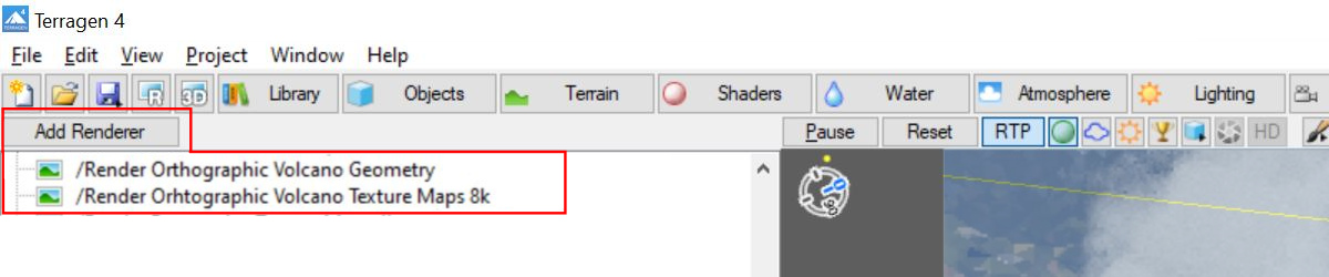
To add a new Render node to the project, click the Add Renderer button at the top of the Render Node list.
Render Layers
One of the abilities of Render Layers is to enable you to save certain render elements as images, which comes in very handy for exporting texture maps. To assign a Render Layer to the render node, click the green “+” button to the right of the Render layer parameter and choose “Create new Render layer”. To open the Render Layer window, click on the same button and select “Go to Render Layer”. Alternatively, you can double click on the Render Layer node in the Node Network to open its window.
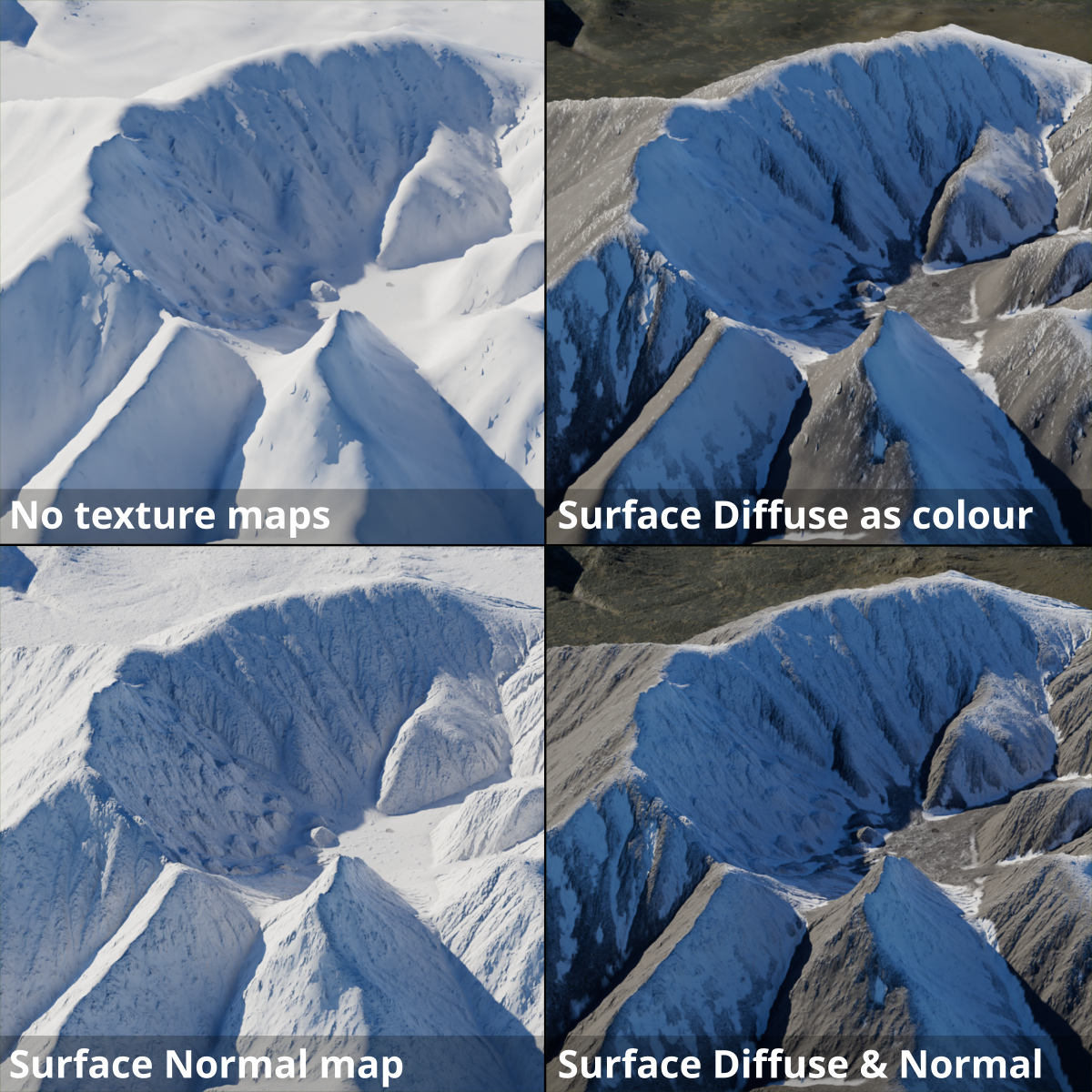
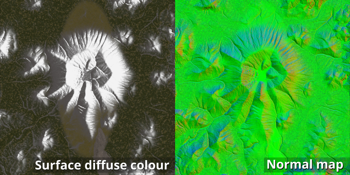
The available render elements are found under the Data section of the Render Elements tab. The “Surface Diffuse Colour (before lighting)” element and the “Surface Normal” element are examples of two commonly saved elements. To select an element to save during the render process, simply check the checkbox next to the render element’s name.
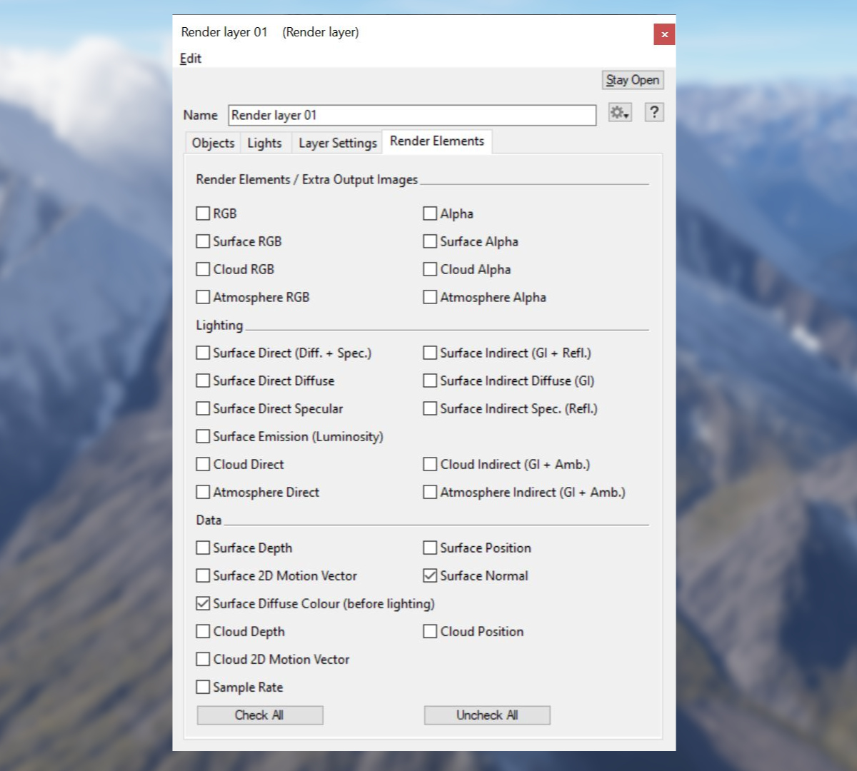
As its name suggests, the “Surface Diffuse Colour (before lighting)” element represents the final colours of the terrain without the influence of any lights. When used as a texture map, it can provide the base colour to the exported terrain.
Embedded in the “Surface Normal” element are the directions in which the micro polygons of the terrain are facing. When used as a normal map for the exported terrain mesh, the micro polygon detail can provide additional details in the terrain.
To access the Render Layer online documentation click on the “?” button in the upper right of the Render layer window.
Texture Quality and Resolution
Texture quality is controlled by the render node’s Image width, Image height, Micropoly detail, and Anti-aliasing parameters. Increasing these parameters will increase the detail in the texture map, but also the time it takes to render the images.
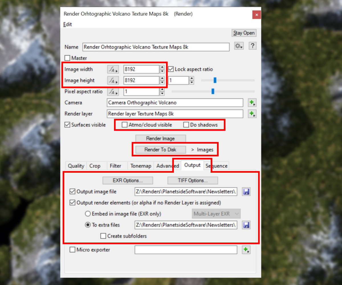
The render elements in the Data section do not rely on the scene’s lighting. You can reduce the time it takes to render these types of images by unchecking the Atmo/Cloud visible and Do Shadows checkboxes, and turning off or disabling the Global Illumination settings as described in the Micro Exporter section above.
To save the selected render elements as individual images, you must check the Output render elements checkbox on the Output tab of the Render node and select the To extra files radio button. Set the location to save the images as well as the file format options found under the EXR Options and TIFF Options buttons. Then click the Render to Disk button to render the images and save them to disk.
Lighting Considerations
While each node in a project contributes to the look of the final render, their use may not be optimal or even necessary when exporting geometry and texture maps. We already saw that it’s a good idea to disable the renderer’s Atmosphere/cloud visible and Do shadows parameters to save render time, but there is another reason too. They affect the quality of the rendered textures. The visibility and brightness of the terrain textures in the RGB channels affects how anti-aliasing and adaptive sampling work, so anything that obscures them can hinder the final quality.
The angle of the sunlight can create a similar issue. The sun might illuminate one side of a terrain feature more than its opposite side. This uneven lighting results in non-ideal texture maps because it can affect how anti-aliasing and adaptive sampling work, resulting in under-sampled (blocky) portions in the texture map.
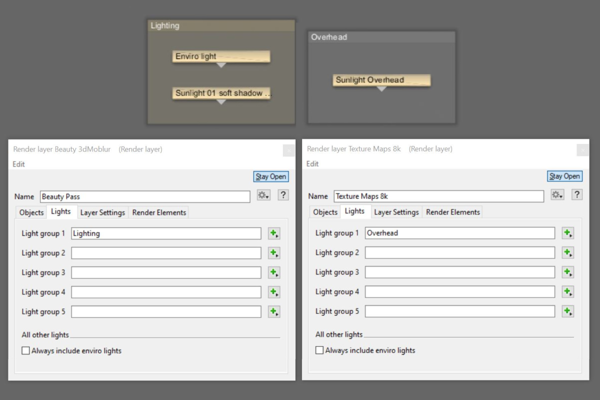
One method to avoid this is to use Terragen’s Render Layer feature to group multiple lighting setups within a single project. These light groups can be isolated during the render process. For example, add another Sunlight node to the project, placing it directly above the terrain and pointing towards it. By default, the new Sunlight node is placed in the Lighting group within the Node Network. Drag it out of that group, and press Ctrl+G or Cmd+G on your keyboard, to place it in its own group. Under the Render Layer’s Light tab, assign the appropriate light group or groups to one of the five Light group parameters for each renderer in your project. In our example, we’ll assign the Overhead light group to the renderer responsible for the texture maps, and the Lighting group to the Beauty Pass renderer. Now, each of these renderers will only use the lights assigned to them.
In Conclusion
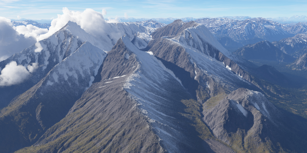
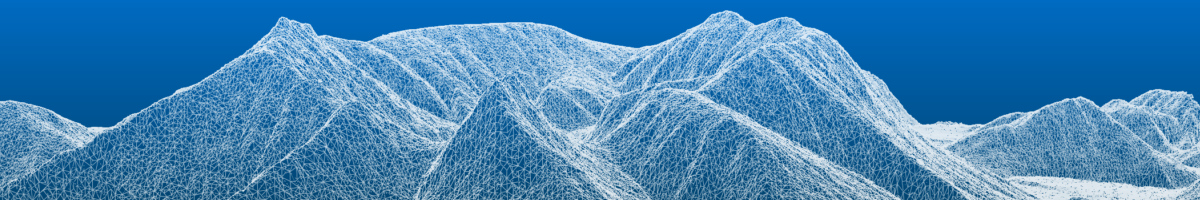
The example image below illustrates how effective the use of render elements can be to enhance the detail of the exported terrain geometry. To learn more about other methods of exporting geometry from Terragen please see this post.