In this series of posts, we’ll explore different techniques to create art-directable terrains in Terragen.
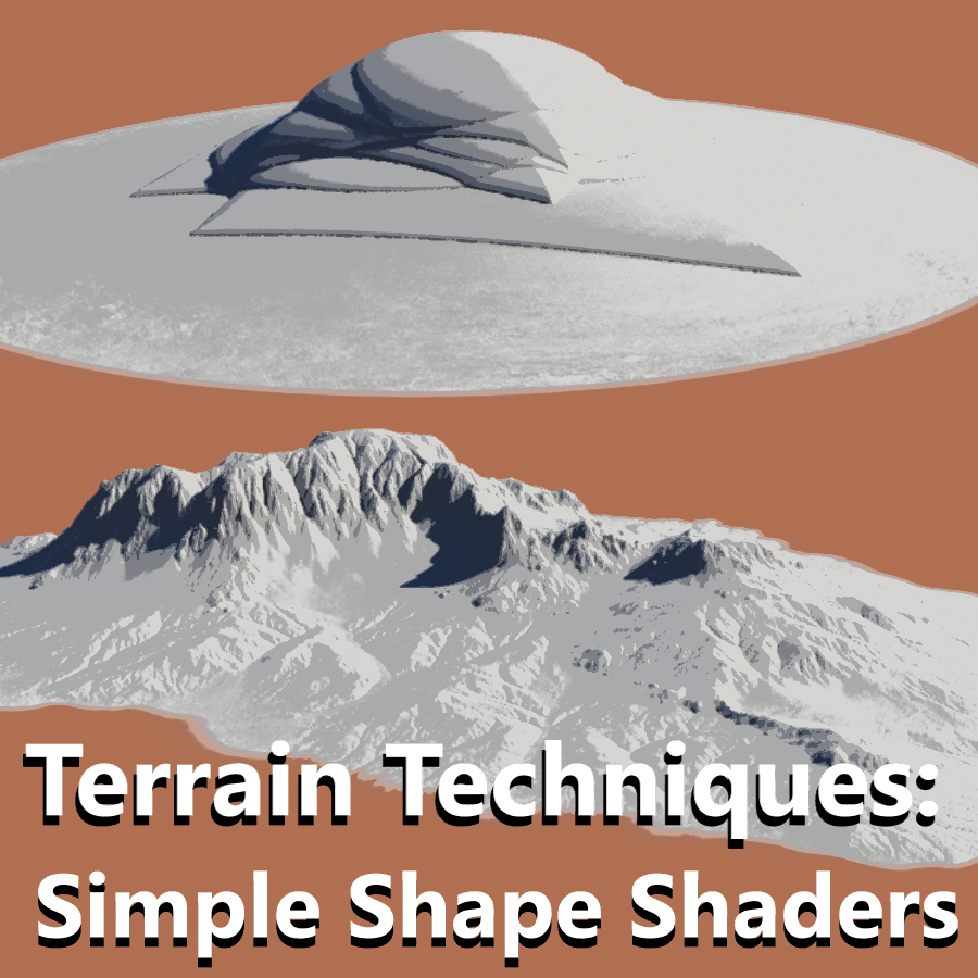
Part 3: Detail, Warp, Erode
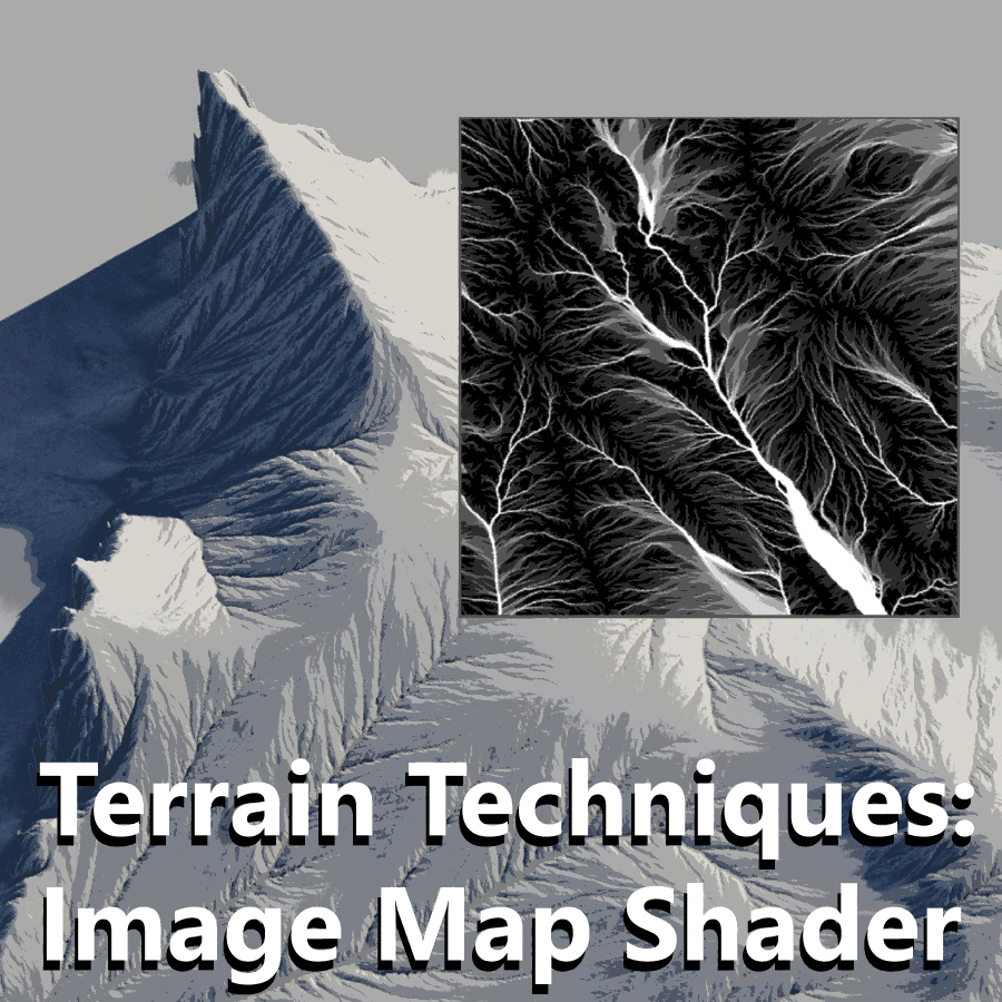
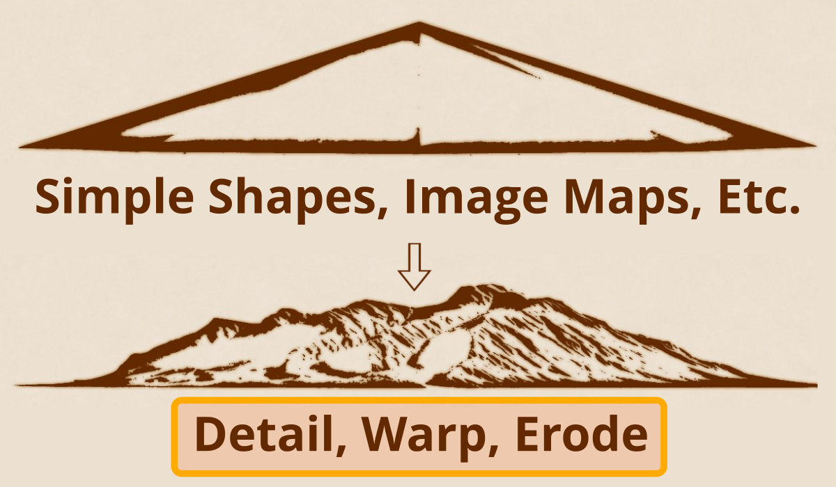
In the previous posts we used Simple Shape shaders and Image Map shaders to create basic forms for a terrain. We then modified the shapes of these forms using various shaders such as Twist and Shear, Fake Stones, and Strata and Outcrops. These forms are easily art-directed; that is to say they can easily be re-positioned and re-sized at any time during this process.
Once the terrain’s layout has been established with these basic shapes, it’s time to transform the landscape into a realistic looking environment. Terragen provides a number of procedural tools to accomplish this, including warp shaders and erode operators.
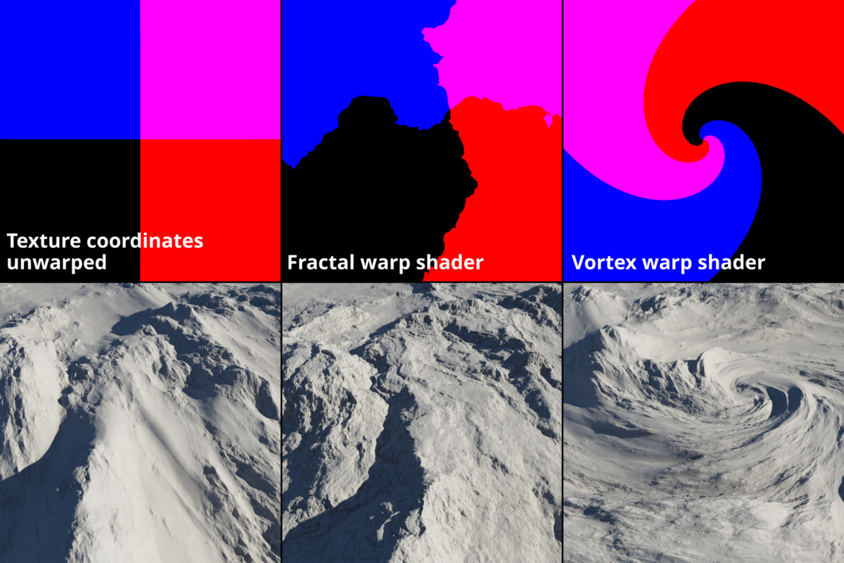
Warp shaders can be used to distort the two dimension texture coordinate space, essentially reshaping the basic form.
Simulating erosion, which is the effect of wind and water on the terrain over a period of time, can also be used to reshape the terrain. Terragen’s heightfield operators give you control over how much erosion takes place and how the eroded material is distributed across the terrain. Additionally, Daniil Kamperov’s Classic Erosion plugin for Terragen is a powerful tool giving you specific control over different types of erosion. The plugin is available at https://daniilkamperov.com/
Distorting Basic Shapes with the Fractal Warp Shader
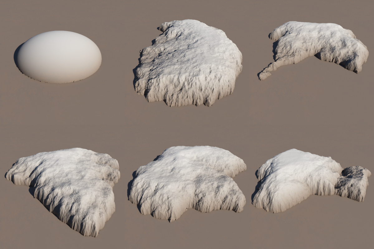
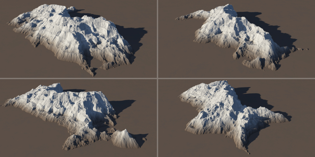
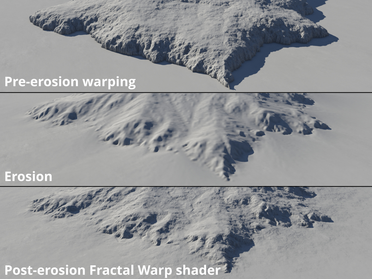
You can create an almost unlimited number of forms suitable for landscapes or terain features by distorting an individual shader or groups of shaders with a warp shader. In the example below, a single displaced Simple Shape shader is distorted into several unique shapes by a Fractal Warp shader.
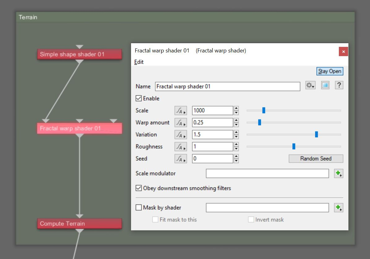
To distort the terrain, you add a Fractal Warp shader directly below the last node used to create the basic shape. The shader will affect all the nodes upstream of it in the workflow.
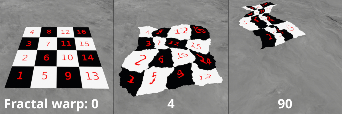
A warp shader distorts the 2D texture coordinates of the shaders connected to its Main input, as illustrated below.
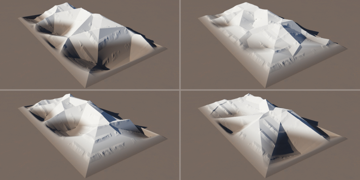
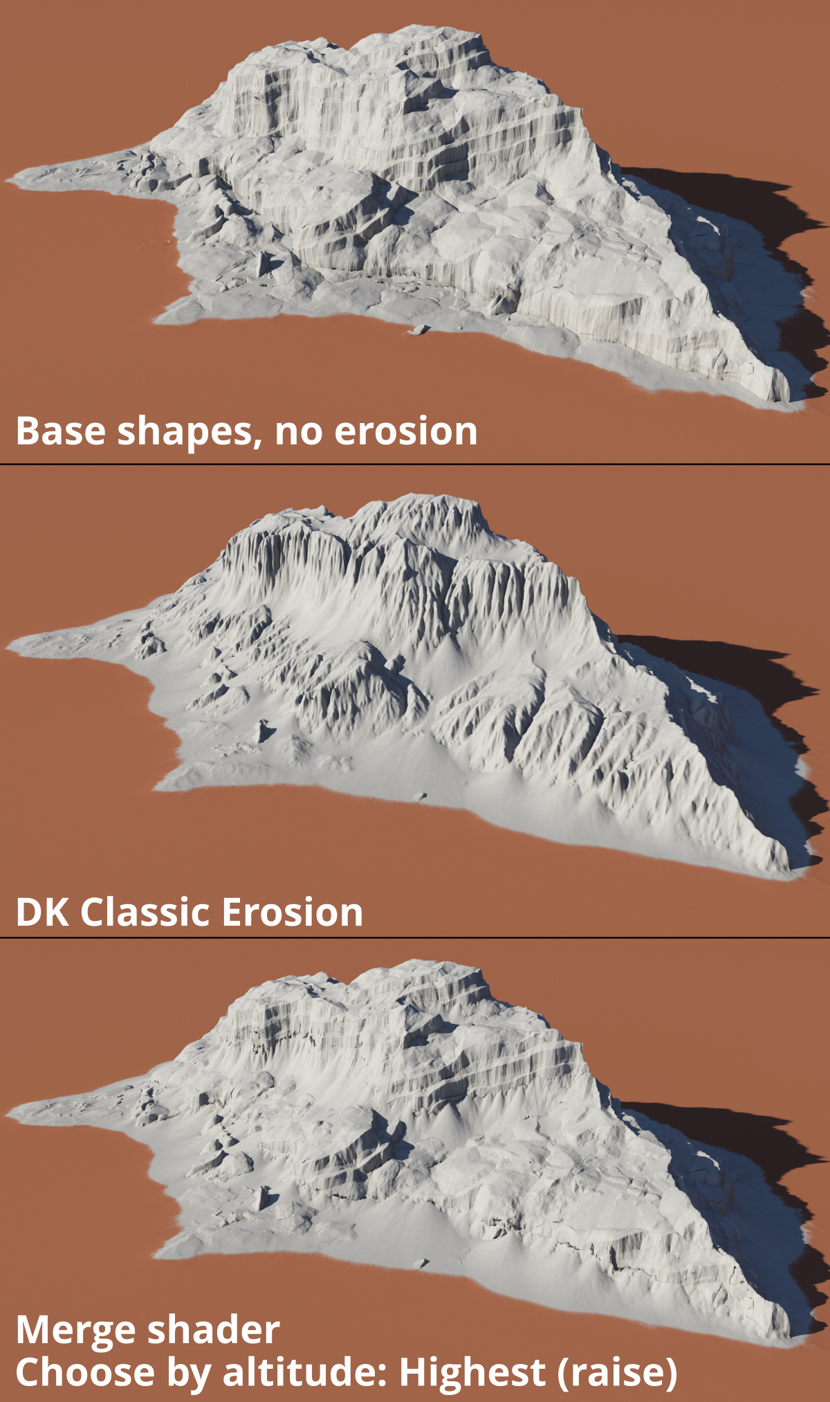
For comparison purposes, these are the types of forms we’re starting with. These forms have no warping or erosion applied to them yet.
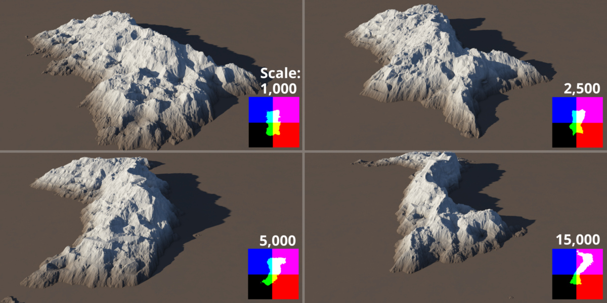
The Scale value sets the size of the fractal noise pattern used to distort the upstream nodes in the workflow. The value is expressed in metres, therefore it’s helpful to keep in mind the size of the shape you are distorting. For example, if your basic shape was 1 kilometer long, setting the value to 250 metres would distort the basic shape several times along its length. Generally speaking, the shape would still remain in its same location. Increasing the value to 10,000 meters, or 10 times larger than the basic shape’s size, would tend to push the shape a considerable distance away from its original location, and distort the shape with a more curved appearance.
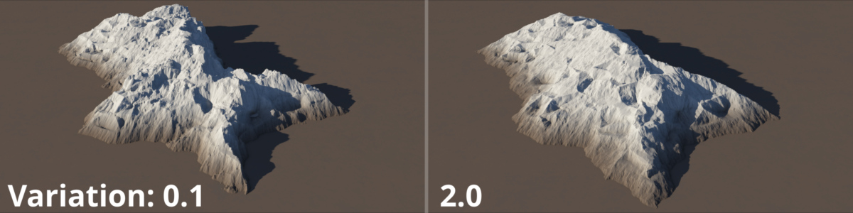
The Warp amount controls the amplitude, or how much distortion occurs. The Variation parameter drives the shape. Lowering the variation value leads to more chaotic distortion, and is a good way to reshape the overall terrain feature into unique shapes..
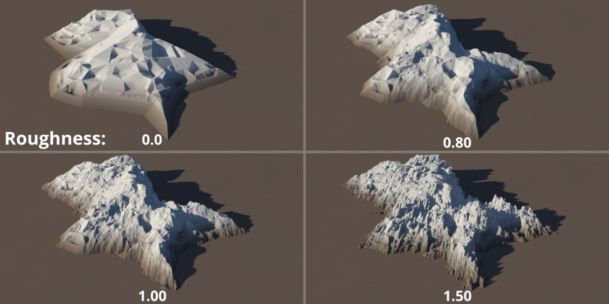
The Roughness setting controls how much contribution the smaller octaves of the fractal noise pattern have, leading to more or less finer detail in the distorted shape. Lowering the values can create blocky detail while increasing it can finer detail. Recommended values for realism are in the 0.8 to 1.0 range.
By changing the Seed value you can create new and interesting forms.
A complete description of the Fractal Warp shader’s parameters can be found in the online documentation here. https://planetside.co.uk/wiki/index.php?title=Fractal_Warp_Shader
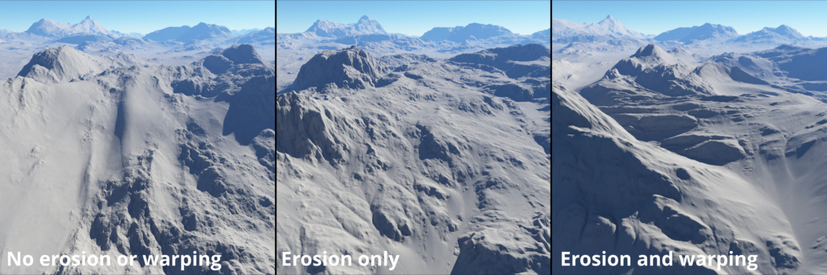
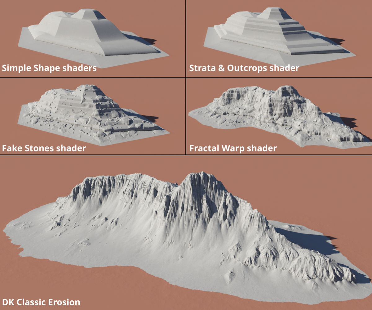
In the example below, you can see the progression of the terrain feature from its initial shape to final shape. The terrain feature was created by stacking a few Simple Shape shaders on top of each other, then modifying the basic shape with the Strata & Outcrops shader, and the Fake Stones shader. Finally, a Fractal Warp shader was applied, and the result eroded with the DK Classic Erosion plugin.
Erosion Methods
Using the techniques described above, you can create complex terrains from just a few shapes. You can further refine the terrain, creating more natural looking features, using the erosion tools available in Terragen. There are two main workflows in Terragen for adding erosion to a terrain. The first is using Terragen’s built-in heightfield erosion operators, such as Erode V3 and Smooth Erode. The second is via Daniil Kamperov’s Classic Erosion plugin. Let’s look at both in some detail.
Heightfield Generation and Erosion Operators
Terragen’s built-in erosion tools work on heightfield data, which contains the elevation values of a terrain. Before we can apply these operators, we need to convert the displaced terrain values into a heightfield using the Heightfield Generate node. Change the 3D viewport to a top view and zoom out far enough to see the entire extent of terrain you created.
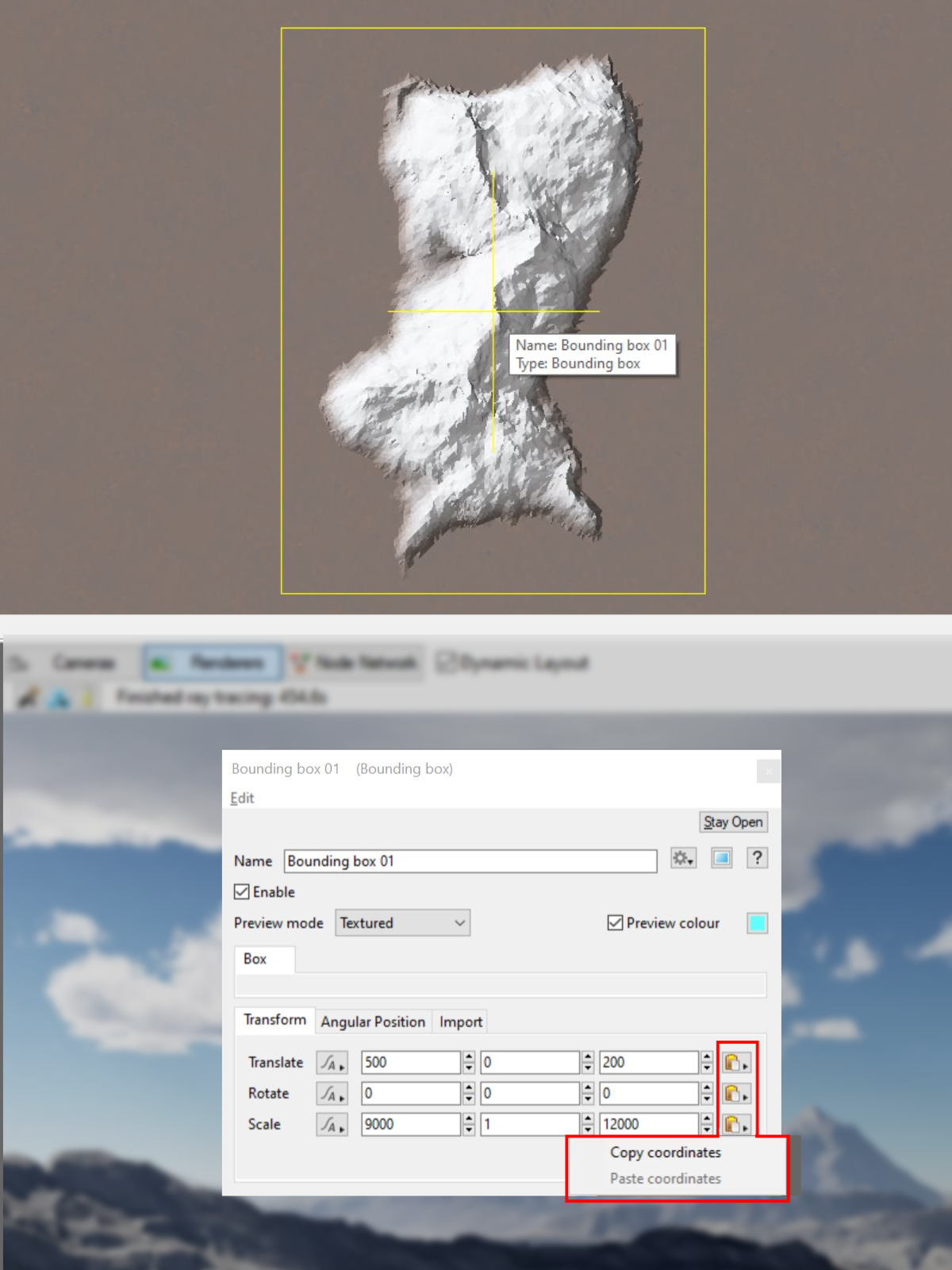
Pro-tip: The Bounding Box
Terragen 4.7 introduced the Bounding Box tool which can be used to provide a visual reference in determining the position and scale values to apply to the Heightfield Generate operator. Add it to your project via the Quick Node Pallette > Bounding Box, Then use the Translate and Scale values to position and scale the box so that it encloses the terrain. These values can be copied and pasted to the Heightfield Generate node via the Copy Coordinates and Paste Coordinates buttons.
Now add a Heightfield Generate node to the project via the Quick Node Palette and double click the node to open its window. Assign the last node used to create the basic form, the Fractal Warp shader, to the Shader parameter. Then check the Position Center button and apply the Bounding Box’s Translate values to the Position parameters. Apply the Bounding Box’s Scale values to the Size in metres parameters.
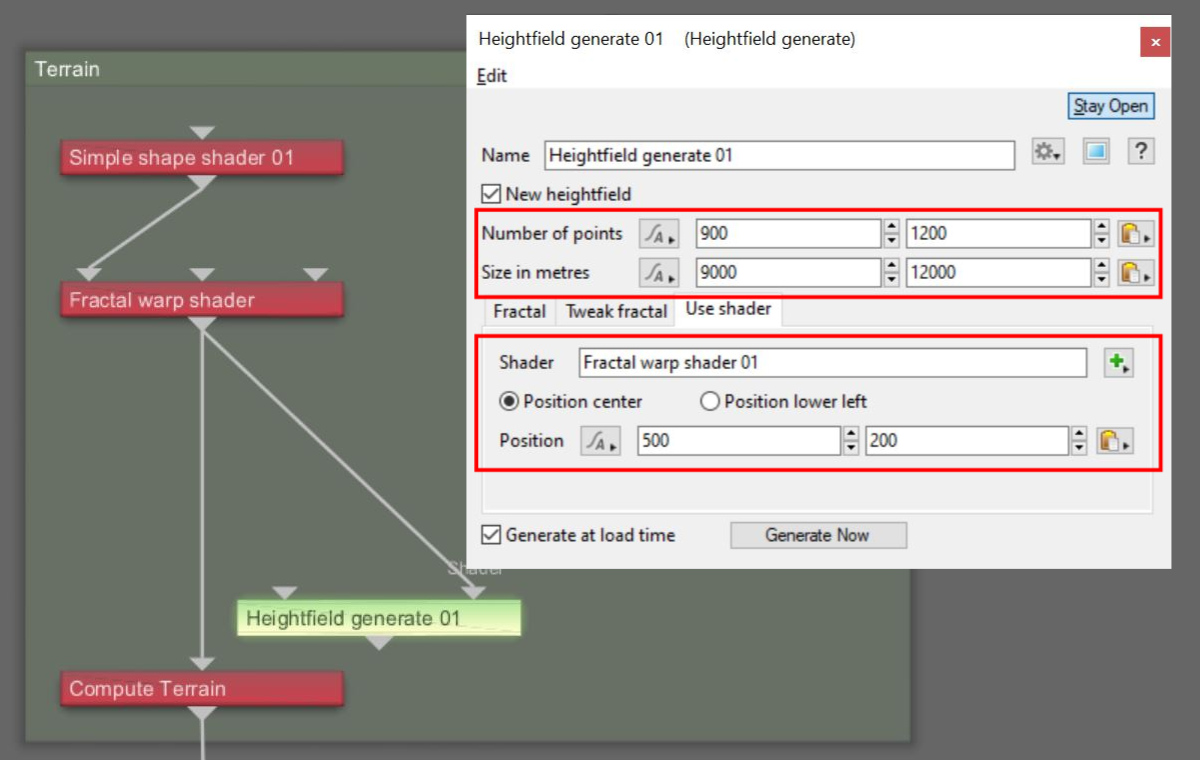
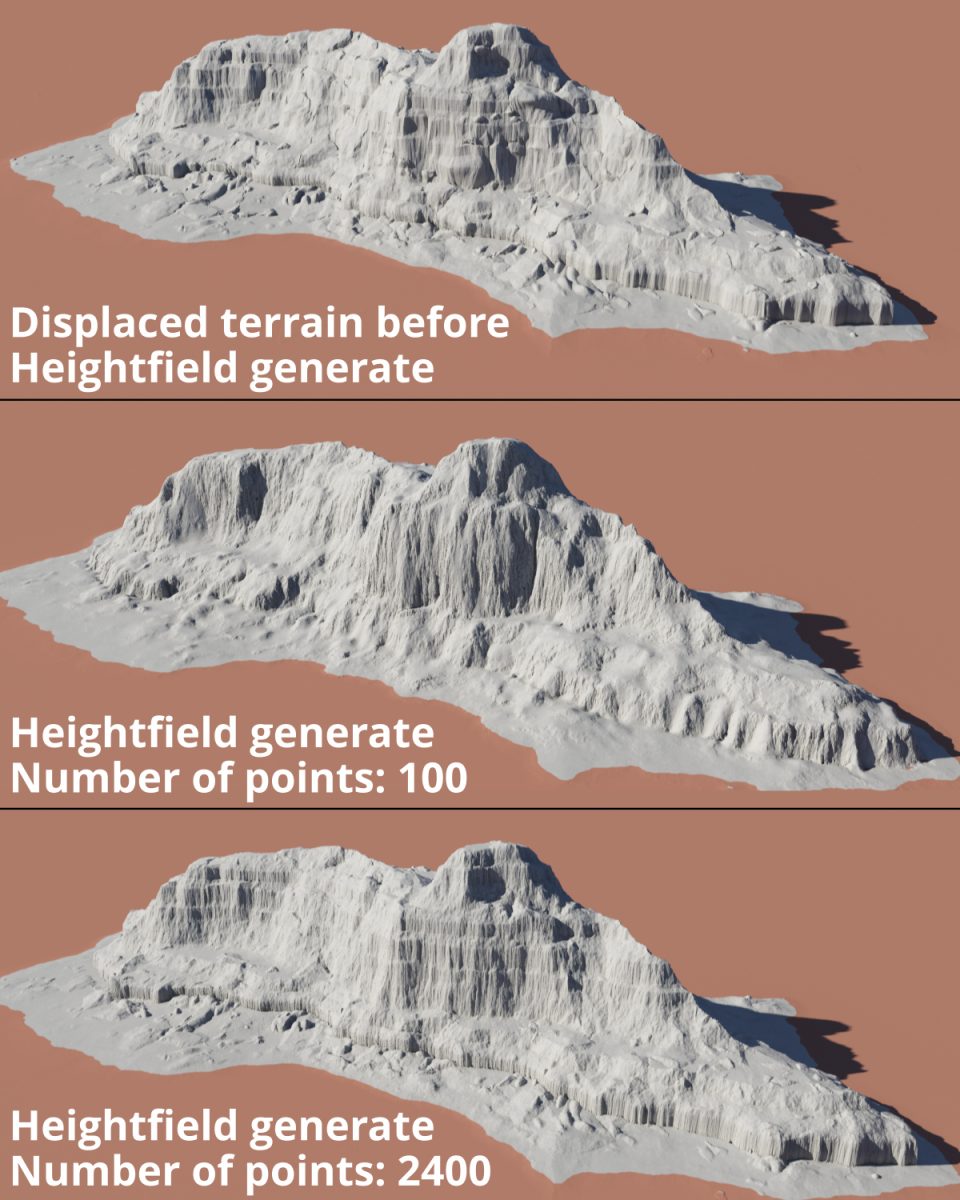
You set the heightfield’s resolution by entering values in the Number of Points parameter. The more sample points in the heightfield, the greater its accuracy to the displaced shape you’ve created. This should be balanced against how much “screen space” the heightfield occupies in the image you’re creating. For example, if the terrain feature is in the distance and occupying one tenth of the frame, it may not be necessary to save the heightfield with 10,000 points when 1,000 points will do.
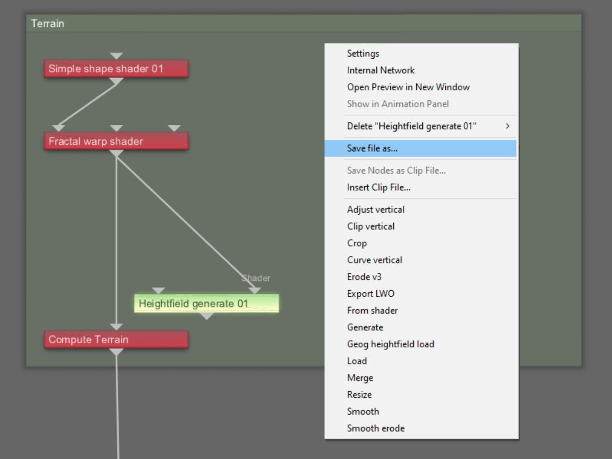
To generate the heightfield, click on the Generate Now button. Once the heightfield has been calculated, right click on the Heightfield Generate node and select Save file as… and save the file.
Pro tip: Saving the heightfield to disk means that you won’t have to generate the heightfield each time you load the project. However, it’s not a requirement that the heightfield be saved to disk. You could add the erode operators directly after the Heightfield Generate node, and bypass saving of the heightfield to disk and loading it back into the project via the Heightfield load node.
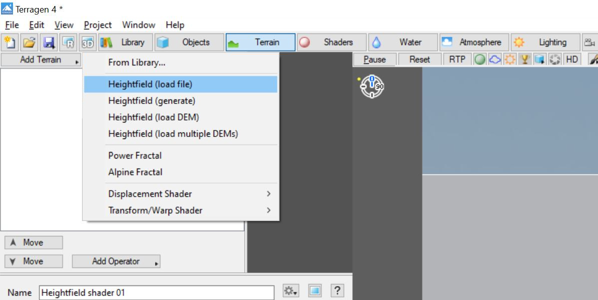
To load a heightfield into Terragen, click the Add Terrain button, choose the Heightfield (Load) option then select the heightfield you just saved. If your heightfield included a positional offset, be sure to open the Heightfield load node and apply the position offset if needed.
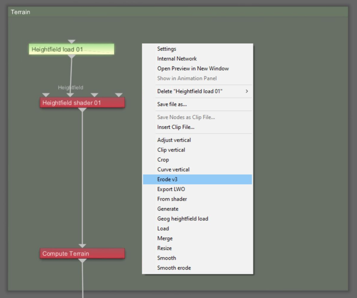
Terragen includes a number of heightfield operators to simulate the effects of erosion, such as Erode v3 and Smooth Erode. When you right click on a heightfield-type node in the Node Network view, a context sensitive menu is displayed and shows you the available heightfield operators. To add an erosion operator to the heightfield, select it from the list and it will be inserted directly below the selected heightfield node.
The Erode v3 operator provides controls for erosion and deposition. Its Flow Distance, Duration, and Erosion power parameters give you control over how much material is eroded, while its Deposition, Deposition rate, and Diffusion parameters give you control over where the material goes.
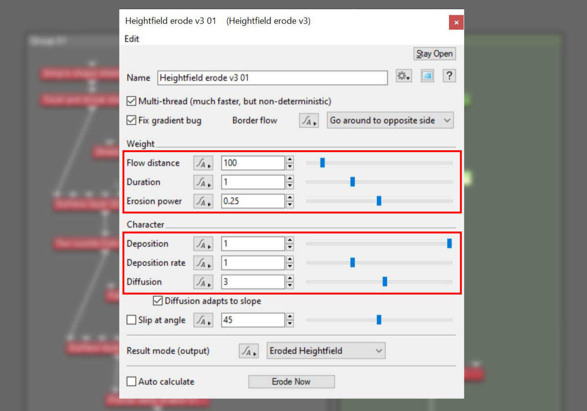
With the release of Terragen 4.8, the Erode v3 operator includes multi-threading optimisation along with other minor improvements. A complete description of the Erode v3 parameters can be found in the online documentation at https://planetside.co.uk/wiki/index.php?title=Heightfield_Erode_v3
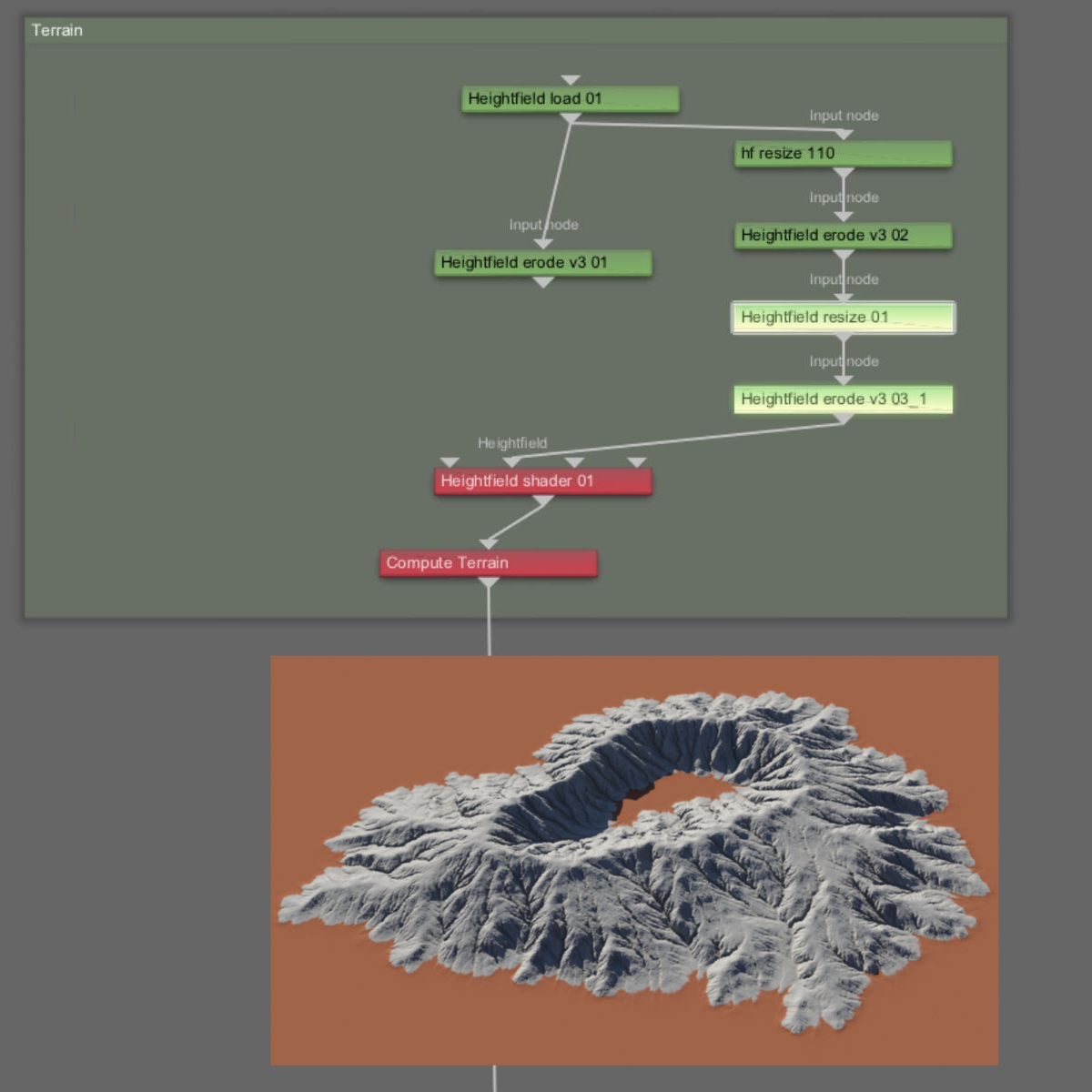
You’re not limited to just one erosion operator per heightfield either. In fact there are occasions when you may want to first re-sample a heightfield at a lower resolution and erode it, then re-sample the results at a higher resolution and erode that with different erosion settings.
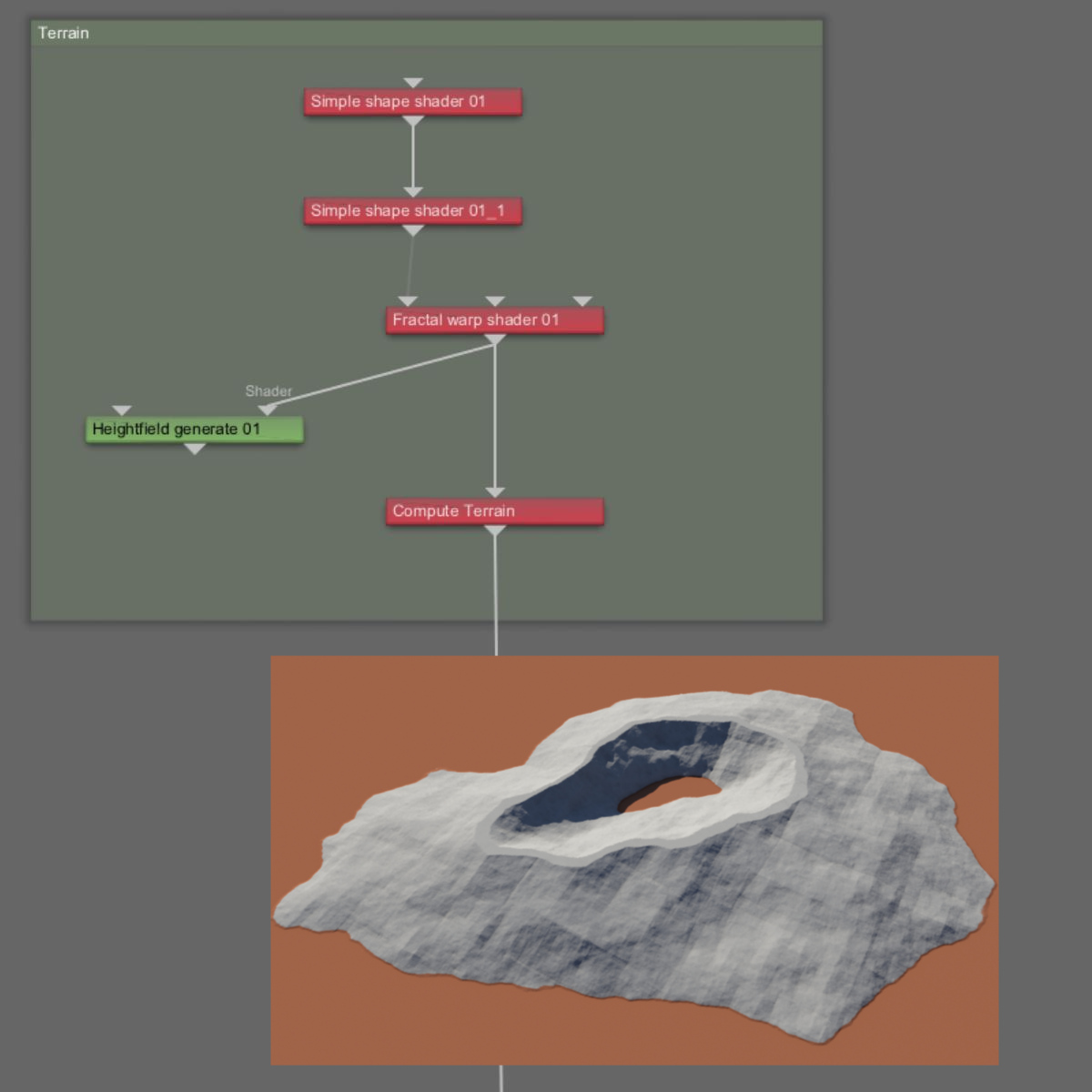
Take the following example. Two Simple Shape shaders have been stacked on top of each other and distorted by a Fractal Warp shader to create a terrain feature approximately 2,200 x 2,200 metres in size. A Heightfield Generate node was used to save the terrain as a heightfield with a resolution of 1,100 x 1,100 sample points. This means one sample point is taken for every two metres of the terrain.
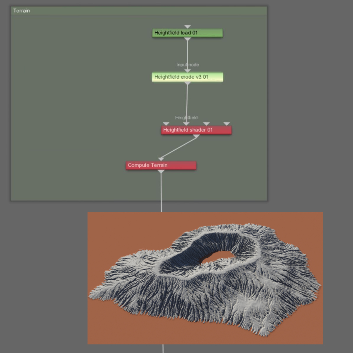
The heightfield is then loaded, and an Erode v3 operator is applied. To see the full effect of the channels created by the erosion process, the deposition parameters have been temporarily set to “0”. In effect, all of the eroded material “disappears” leaving only the eroded channels.
As you can see in the rendered image, many channels were created by the erosion process, conforming quite nicely to the basic shape of the terrain. Note how the flatter areas near the top of the peak have not been eroded as much, because there was enough resolution in the heightfield to preserve this aspect of the basic shapes that formed the terrain in the first place.
In Terragen you can re-sample a heightfield using the Heightfield Resize operator. This allows you to dynamically raise or lower the number of points being sampled from the heightfield.
In the next image, the Heightfield Resize operator re-samples the heightfield by ten percent, or 110 x 110 sample points. With fewer samples to work with, the erosion operator calculates a different erosion solution, one that is coarser and has fewer channels. Note how the flatter area near the top of the peak are no longer flat but conform to the slope of the erosion process.
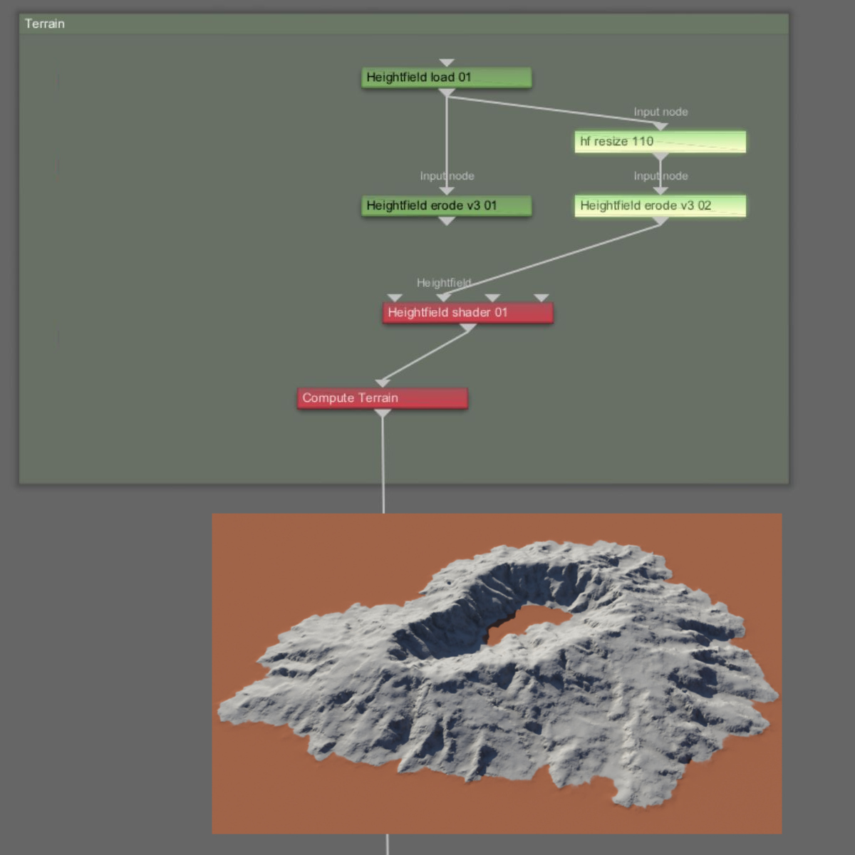
You can now re-sample the eroded terrain with another Heightfield Resize operator. This time increasing the amount of resolution so that subsequent operators have more sample points to work with. In this example, we’re re-sampling the eroded terrain at 1,100 x 1,100 sample points. We then apply another erosion operator.
Note in the next image, how the branching results are more pleasing and natural by using the two combined erosion processes.
Daniil Kamperov’s Classic Erosion
A second approach to the erosion workflow involves the use of Daniil Kamperov’s Classic Erosion plugin for Terragen. The plugin is currently available on the Windows platform and more information about obtaining it may be found online at https://daniilkamperov.com/.
The plugin includes its own Heightmap generator, therefore you can connect your shader network directly into its Main Input, by-passing Terragen’s heightfield generation process.
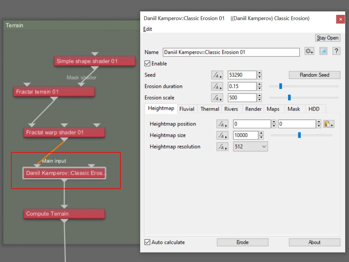
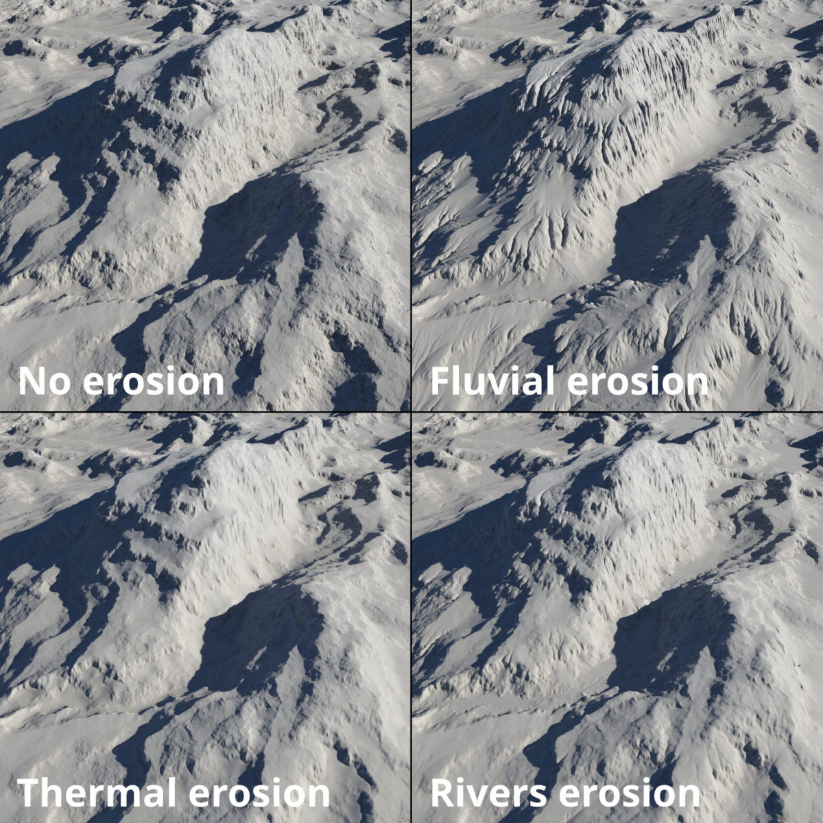
Among its many features, DK Classic Erosion includes several erosion algorithms, including fluvial, thermal and rivers erosion.
The DK Classic Erosion plugin also has the ability to export erosion data as image maps. We’ll look more at this feature below.
It should also be noted that the two workflows we’ve described are completely compatible with one another and may be used in the same project. For example, you could use heightfield operators to modify the terrain features and then apply DK Classic Erosion to the entire terrain.
Merging Heightfields and Shader Networks
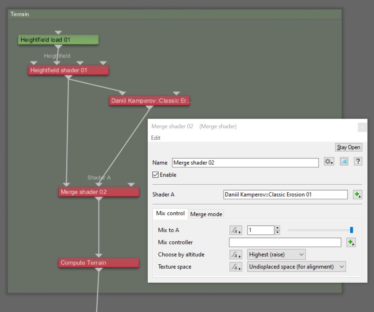
There may be situations in which you want to combine the original terrain, before it has been eroded, with the eroded terrain. Terragen’s Merge shader provides ways to do this. You can mix shaders together in a variety of ways, such as based on the highest or lowest altitude feature.
In the example image below, the Heightfield shader contains the non-eroded terrain, which is output to the DK Classic Erosion shader. The two shaders are then combined together via the Merge shader, which mixes the two based on the Highest altitude feature.
Post Erosion Detail
When a heightfield’s resolution is too small, the details may get lost during the erosion simulation. There are many tools in Terragen to add subtle details back into the terrain following the erosion process, such as the Strata and Outcrops shader, and the Fake Stones shader. You could also add another Fractal Warp shader to the project following the erosion nodes in order to add fractal noise detail back to the eroded areas of the terrain. You can even add populations of 3D objects.
Let’s look closer at how we can use data from the erosion process itself to add post erosion detail back into the terrain.
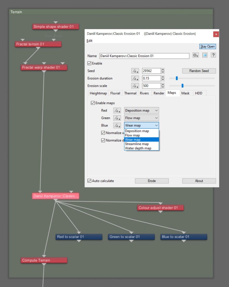
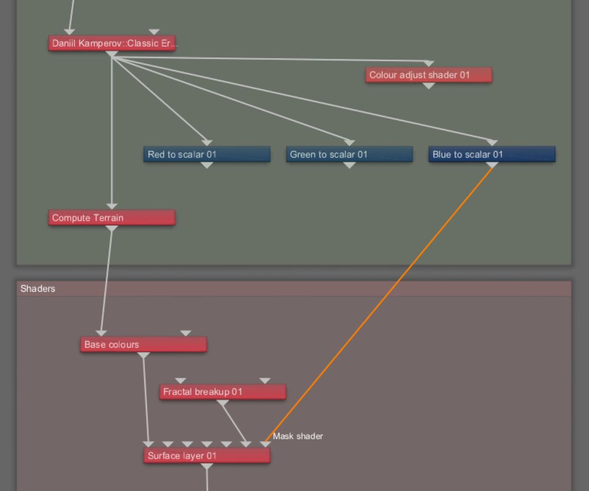
The DK Classic Erosion plugin for Terragen has the ability to export several types of data including deposition, flow, and wear. The data can be saved to disk within the RGB channels of an image map, or sampled from the shader’s own output by Terragen’s function nodes, such as the “Red to scalar” node. In either case, the data can then be used to mask areas of the terrain for other operations.
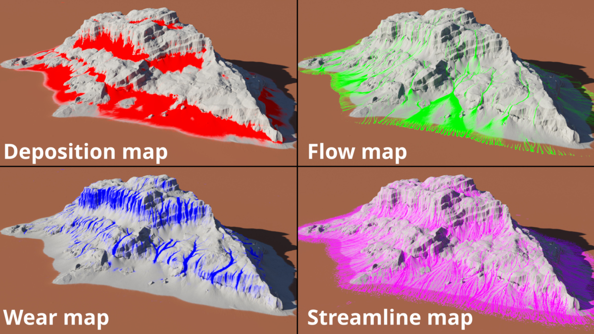
Here is a visual representation of the maps available as output from the DK Classic Erosion node.
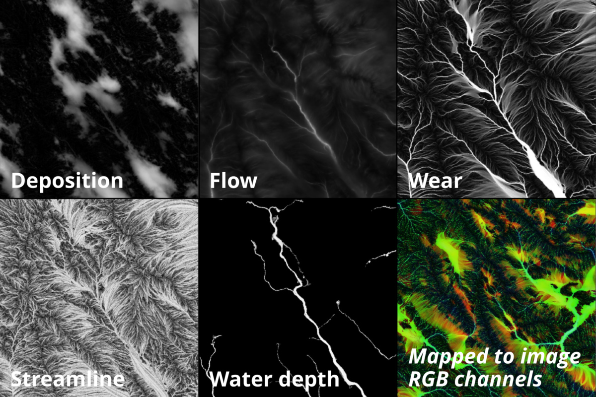
These maps can be used “as is” or combined in various ways to create masks. To see where the influence of a particular map is upon the terrain, you can assign one of the maps to the Mask shader input of a Surface Layer shader.
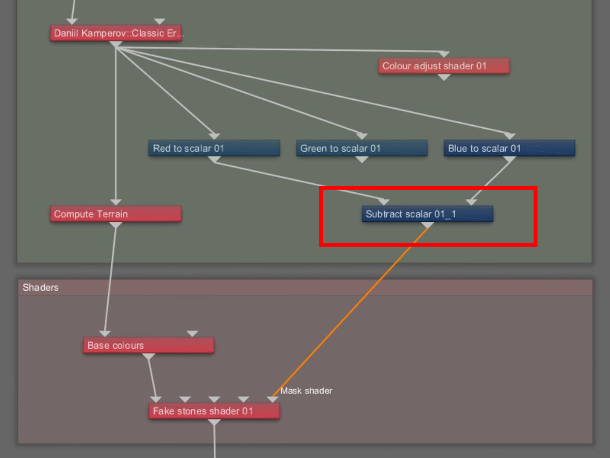
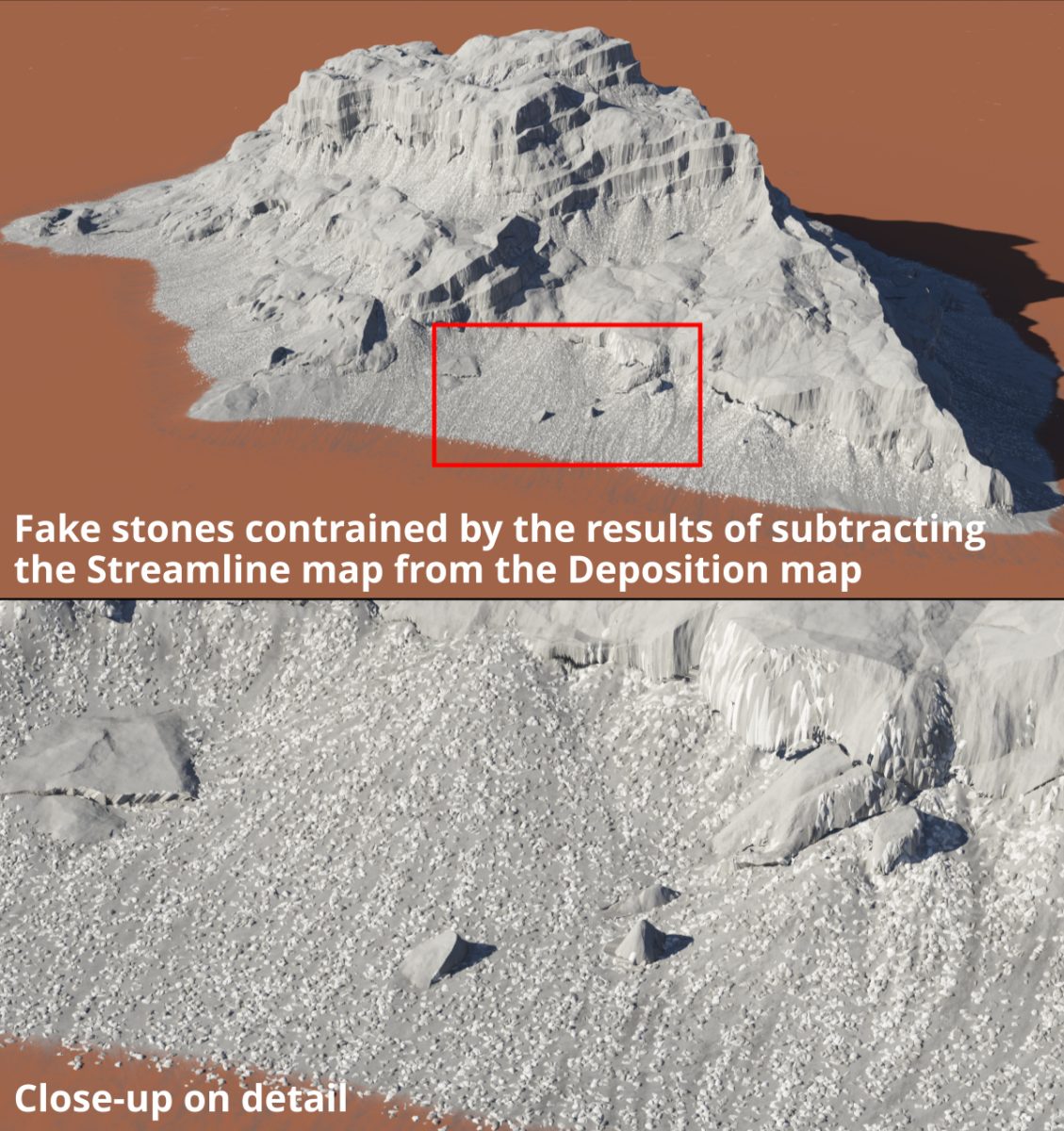
You can create variations of these masks to suit your needs by mathematically combining the map values together using Terragen’s blue function nodes. For example, if you wanted the talus areas of the eroded landscape to be made up of small rocks, but not in the areas where water may have trickled down, you could create a new mask by subtracting the streamline map from the deposition map via the Subtract scalar node.
Try It For Yourself
Click here to download a Terragen 4 project file that includes examples and step-by-step instructions the workflow described in the Simple Shape shader post, or here for the workflow described in the Image Map shader post.
Other Posts In This Series
The focus in these blog posts has been on creating art-directable terrain. Building up complex terrains from basic shapes provides you the ability to return to the starting shape, or a previous step, and make adjustments to its position and scale within the project. Warping the base shapes can create an almost unlimited number of variations of the shape. Adding erosion and post-erosion details can create realistic terrain features from a simple basic shape.
Be sure to check out these other blog posts in our Terrain Techniques series.