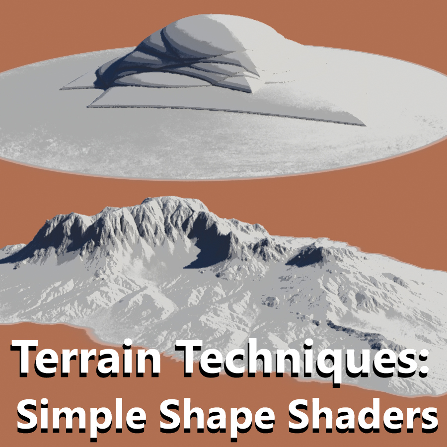
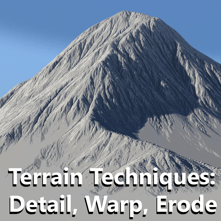
In this series of posts, we’ll explore different techniques to create art-directable terrains in Terragen.
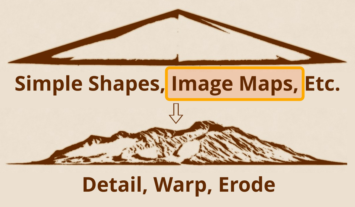
Part 2: Image Map Shaders
Image maps play an important role in computer graphics by storing many forms of data including colour, height, surface normals, and z-depth information to name just a few. In this post, we’ll look at how an image map can be used to displace the surface of the terrain in Terragen, and create interesting topography.
You can think of an image map as being an individual “set piece”, or already assembled into an entire terrain, as shown in the example below. Image maps are easily duplicated, resized and moved about in your project.
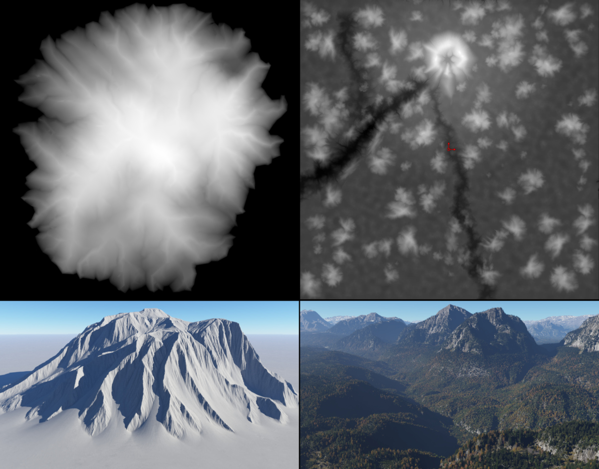
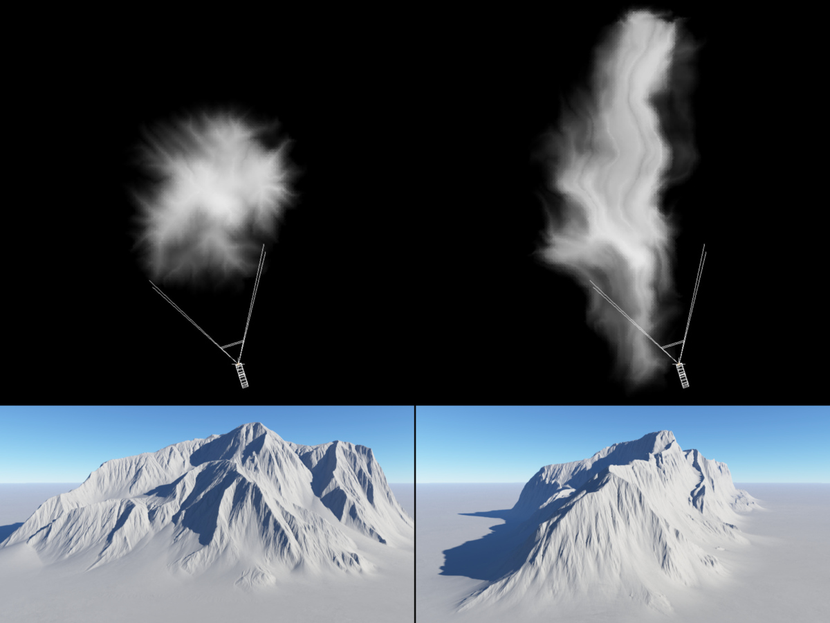
You can create image maps in many paint programs and 3D applications which are suitable for displacing the planet surface in Terragen. Here’s two examples, where the brightest areas in the image represent the highest peaks of the terrain.
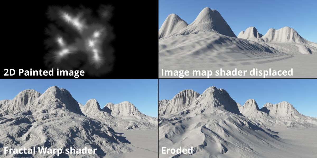
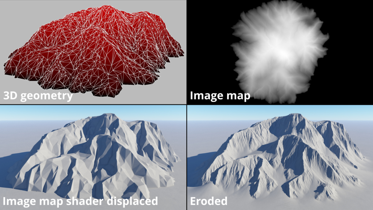
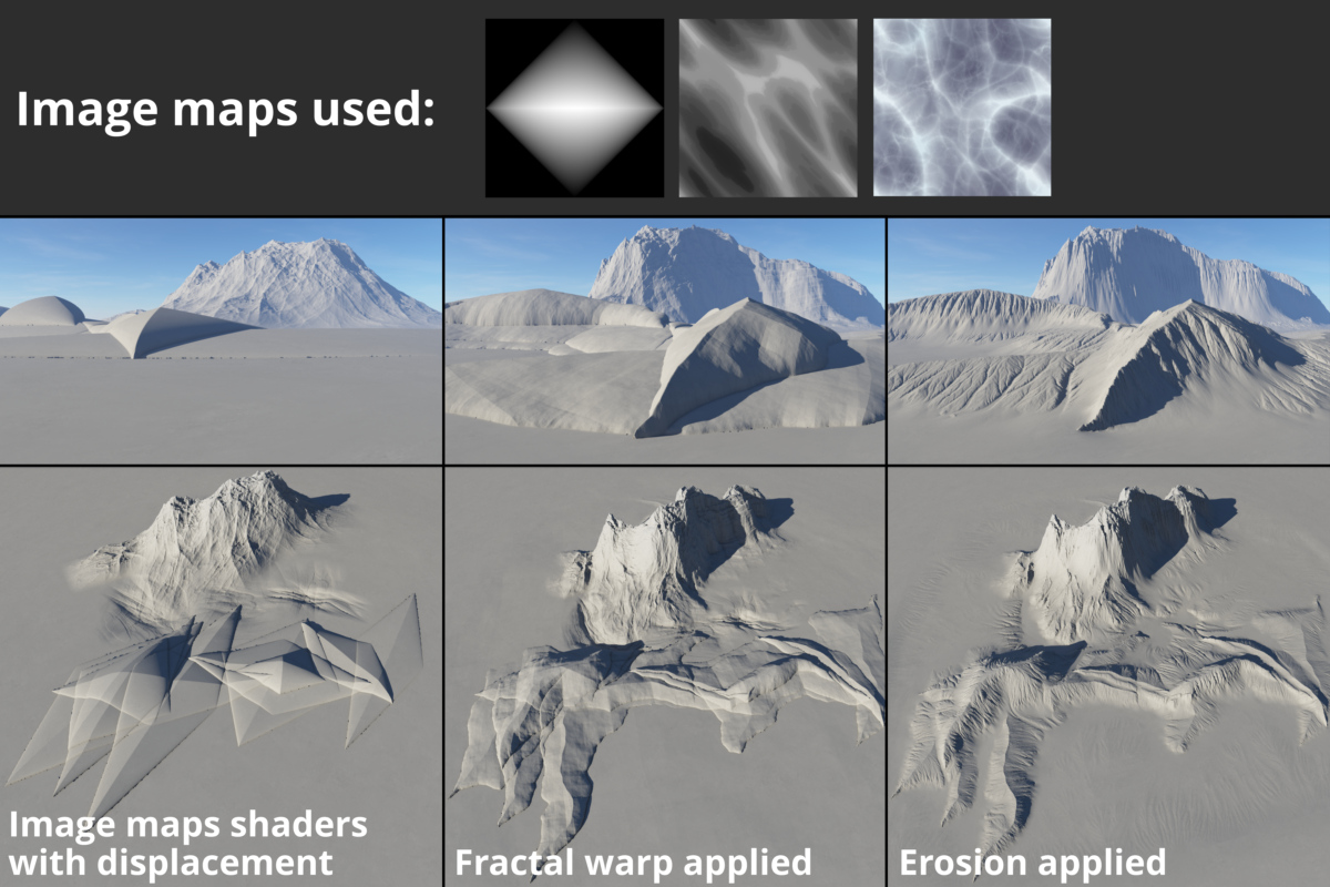
Like the Simple Shape shaders in the previous blog post, images can be distorted by warp shaders to create new and interesting variations. Likewise, once the surface of the terrain has been displaced, erosion operators may be applied. We’ll discuss the warping and erosion tools in a separate blog post.
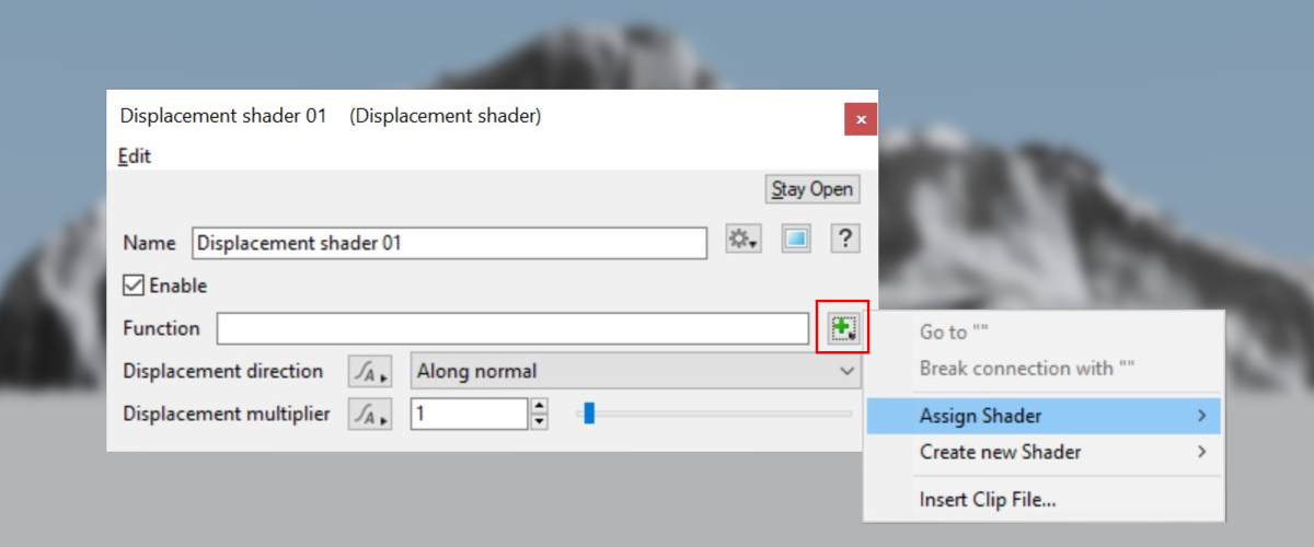
In Terragen, you load external images into your project by means of the Image Map shader. Many of Terragen’s functions allow you to assign an Image Map shader to it, by clicking on the Load button to the right of the parameter.
Alternatively, you can add an Image Map shader to the project by bringing up the Quick Node Palette and selecting the shader from the list. For more information about the Quick Node Palette please see the previous post in this series, Terrain Techniques – Simple Shape Shaders.
Projection, Location Tab
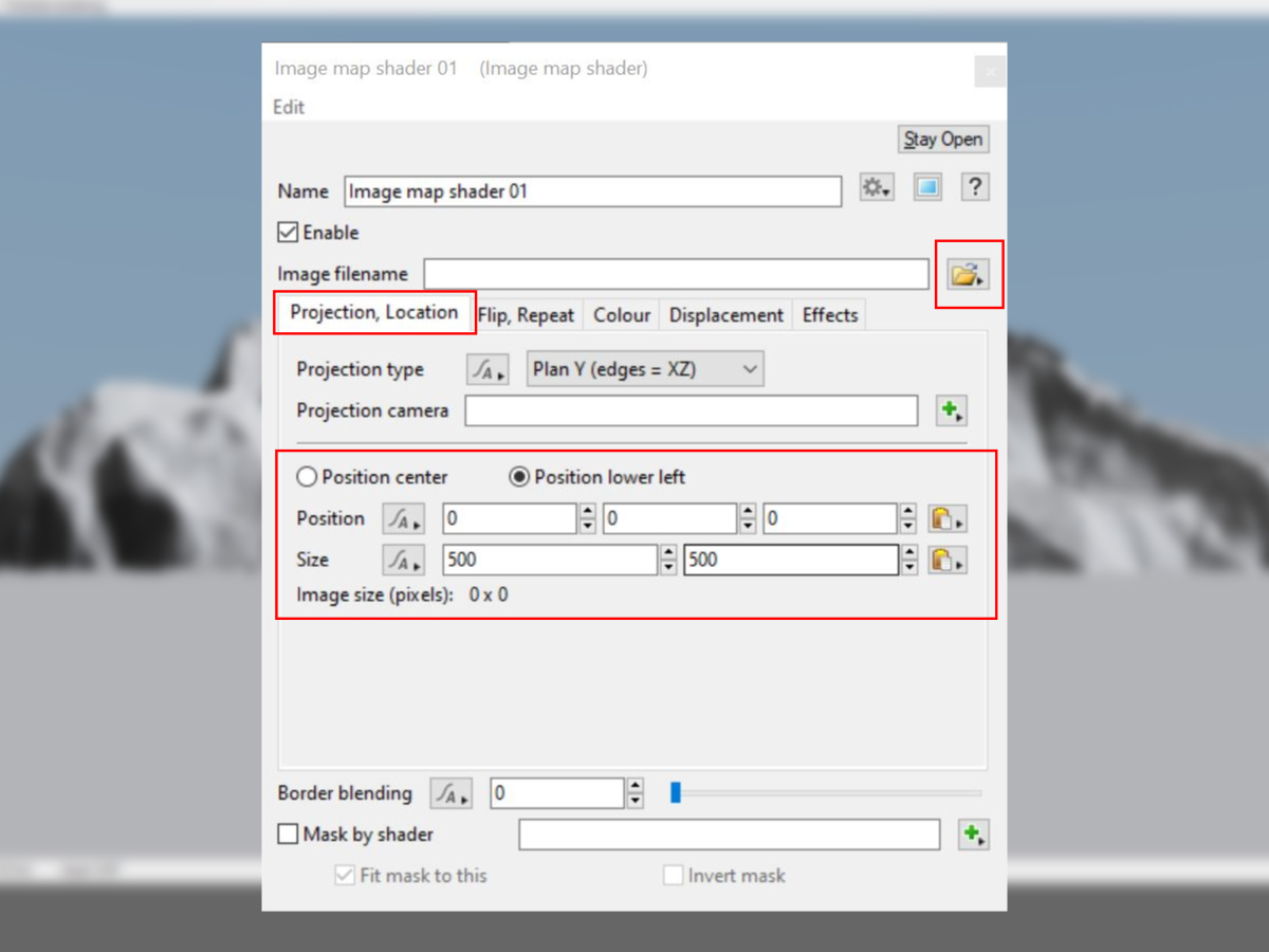
With the shader’s window open, you can click on the button next to the Image filename parameter to open and select the image of your choice. By default, the Projection, Location tab is displayed and this is where you can position the image in the scene by entering values in the Position parameter. In addition, you can define the area that the image map covers with the Size parameter. You can scale the image non-uniformly by entering different values in each of the Size parameter fields. The Position center and Position lower left radio button determine how the image is aligned.
Displacement Tab
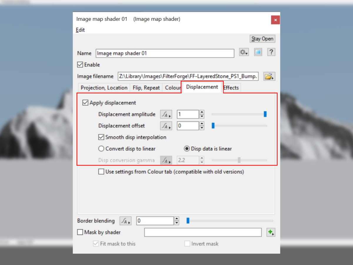
In order for the image map to displace the terrain, first check the Apply displacement checkbox under the shader’s Displacement tab. Then enter an amount to displace the terrain in the Displacement amplitude field. The value should be expressed in metres. Internally, the Image Map shader multiples the Displacement amplitude value by the pixel value in the image then raises or lowers the surface of the terrain appropriately.

If you want the displacement to be based on the raw data in the image map leave the Disp data is linear parameter checked. Should you wish to override those values you can check the Covert disp to linear radio button. When the Convert disp to linear button is enabled, the Disp conversion gamma parameter becomes available with a default value of 2.2. Visually speaking, lowering this value raises the terrain in the darker areas of the image, while raising the value can sharpen or emphasize the brighter values in the image map.

More Control Over Height Values
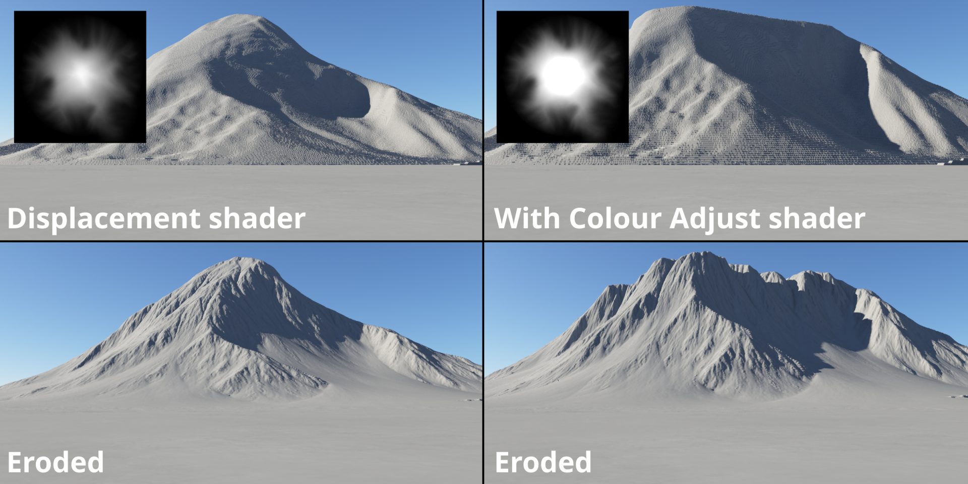
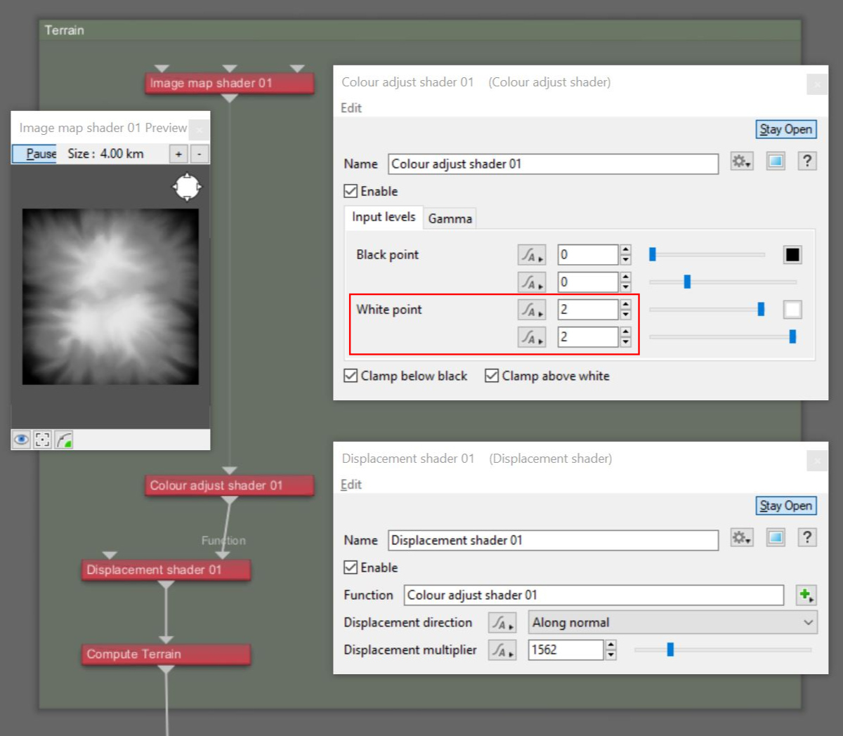
For even more control over the shape of the displaced terrain features, you can modify the pixel values in an image before displacing the terrain. In the example below, a Colour Adjust shader is used to change the pixel values, giving the terrain a flatter plateau-like top.
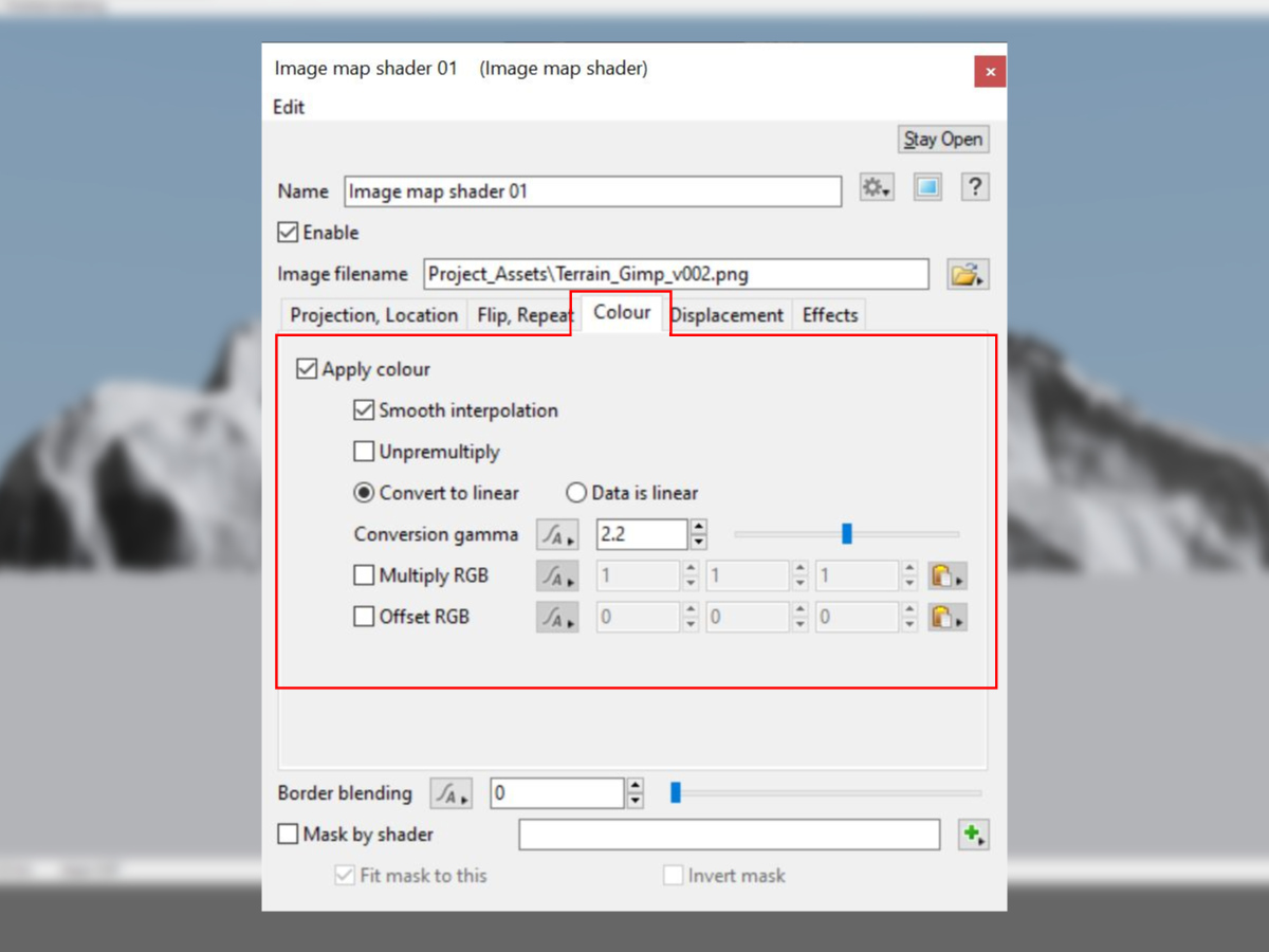
In this situation, instead of using the parameters on the Displacement tab to directly displace the terrain surface, you would use the parameters under the Colour tab and add a Displacement shader to the project. This allows the colour values provided by the image map to be modified by shader or function nodes prior to displacing the surface. Between these two shaders, you can insert any shader or function nodes to modify the colour output from the image.
The image of the Node Network below illustrates this workflow by inserting a Colour Adjust shader between the Image Map shader and a Displacement shader, changing the White point value from 1 to 2.
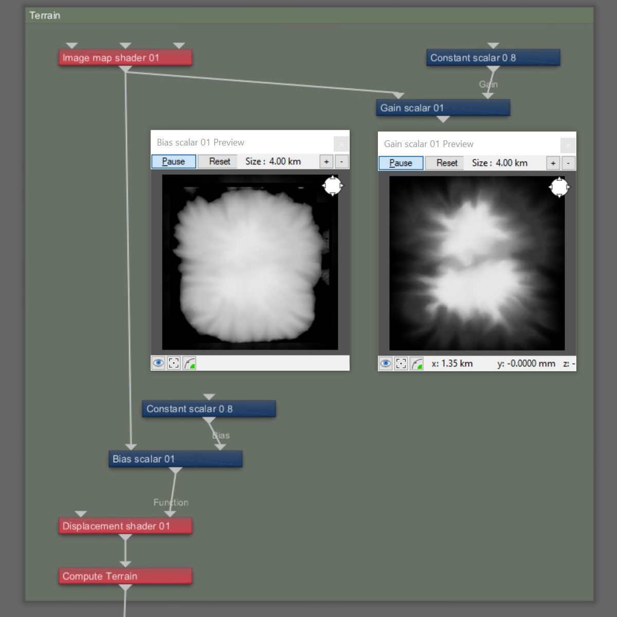
The pixel values in the image can also be manipulated by Terragen’s blue function nodes. Two examples are shown below using a Gain scaler node and a Bias scalar node to reshape the colour values based on a curve. Additional information about these function nodes and other may be found in Teragen’s online documentation at https://planetside.co.uk/wiki/index.php?title=Main_Page.

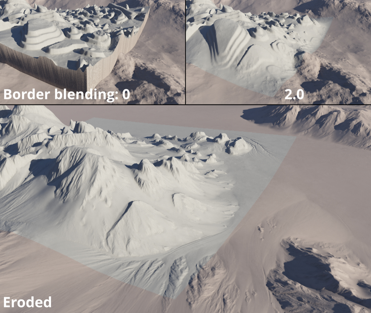
The Border blending parameter, located near the bottom of the UI can be used to blend the edges into the existing terrain. This can create smoother transitions between the shader and the existing terrain features.
Putting The Pieces Together
Let’s explore a few ways in which to use the Image Map shader to create art directable terrains. Using the example image of the mountain above as a “set piece”, you can block out a larger terrain by simply duplicating, scaling and repositioning the Image Map shader. Keep in mind that negative displacements work as well, to create depressions, crevasses, canyons and valleys in the terrain. To rotate the image, add a Transform Merge Input shader directly below the Image Map shader and modify the rotation’s “Y” axis value via the Rotate shader parameter. You can further manipulate the scale and position via the Translate shader and Scale shader parameters.
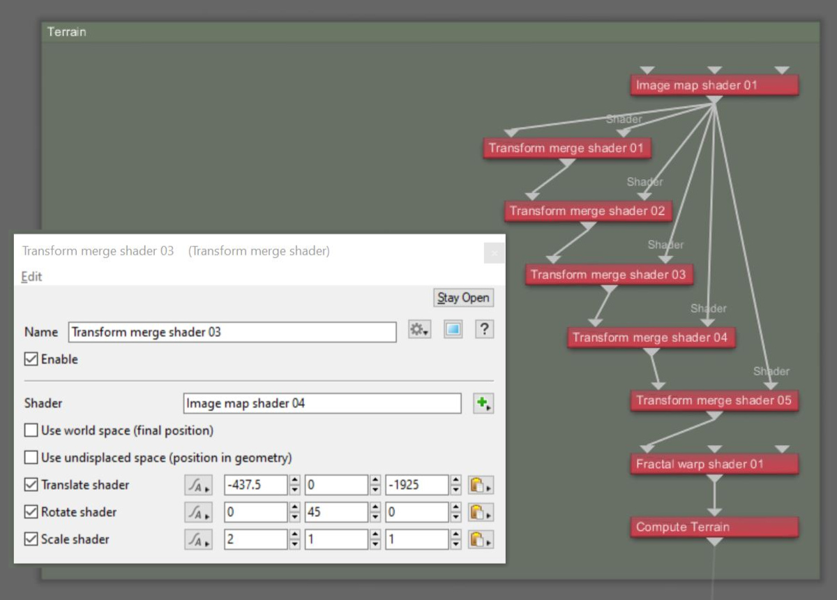
Here’s an example of terrain created by duplicating the Image Map shader six times, and modifying each shader’s parameters.
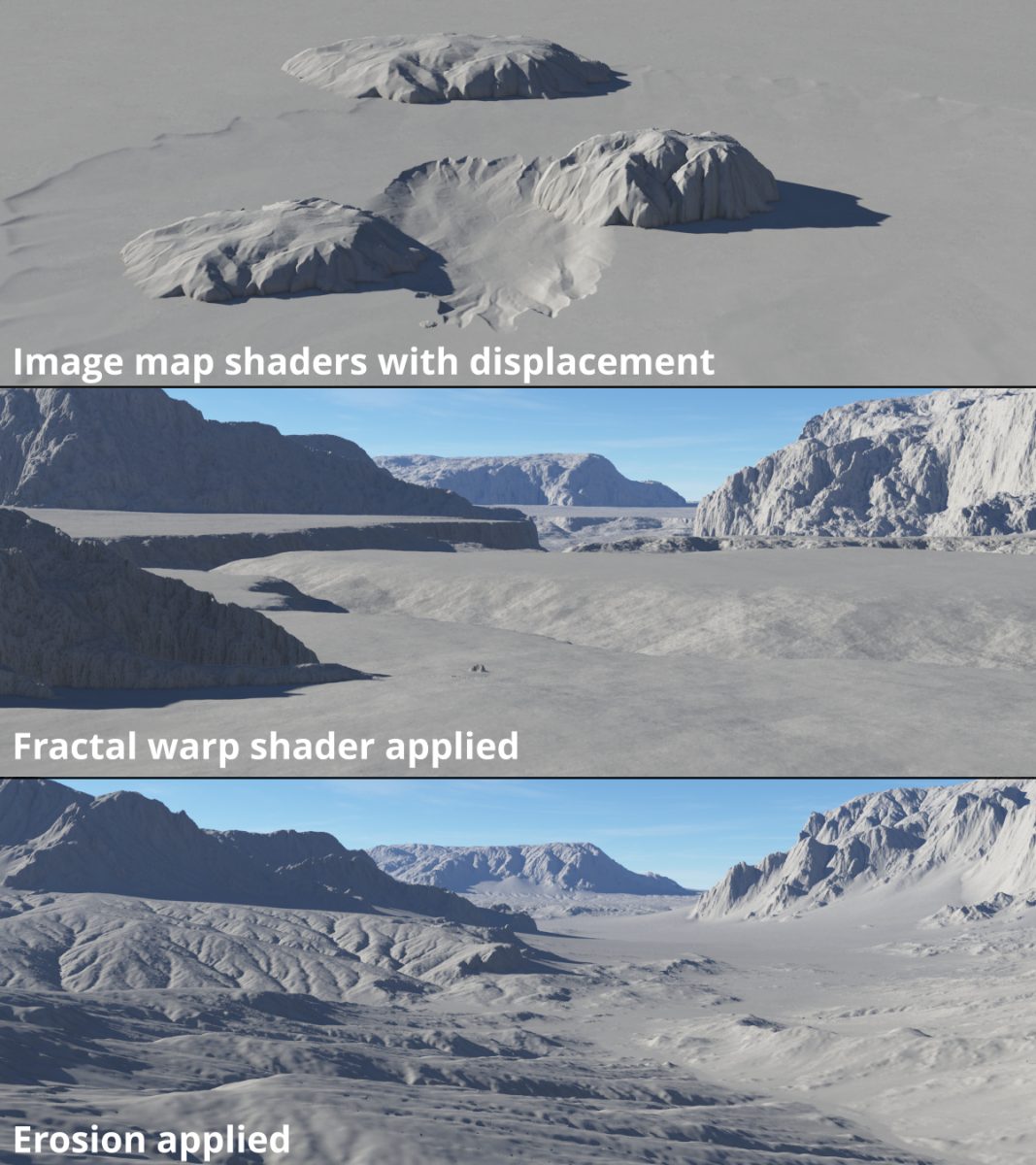
As an alternative to positioning individual Image Map shaders for each terrain feature in Terragen, you could use a paint or compositing program to combine them into one image.
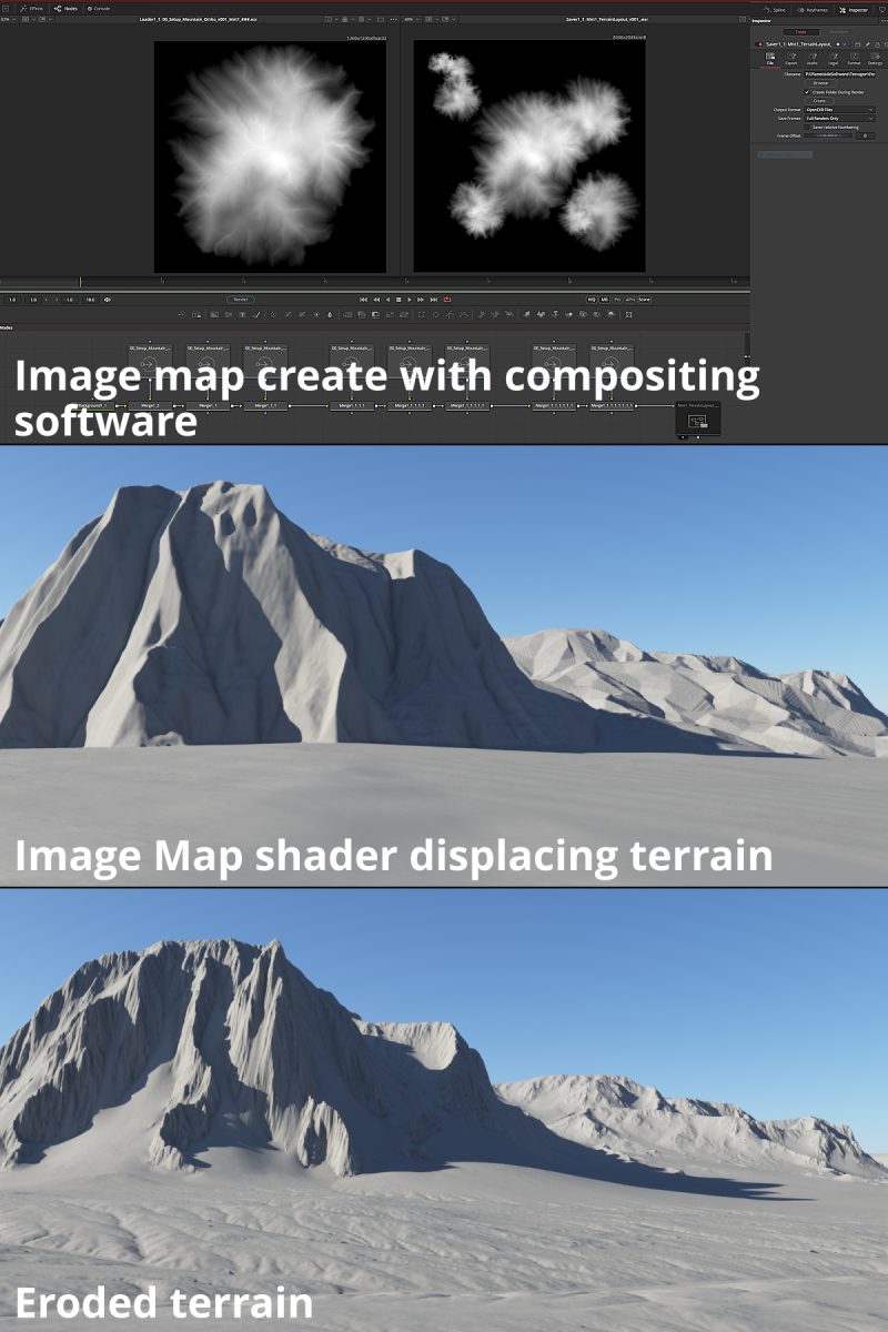
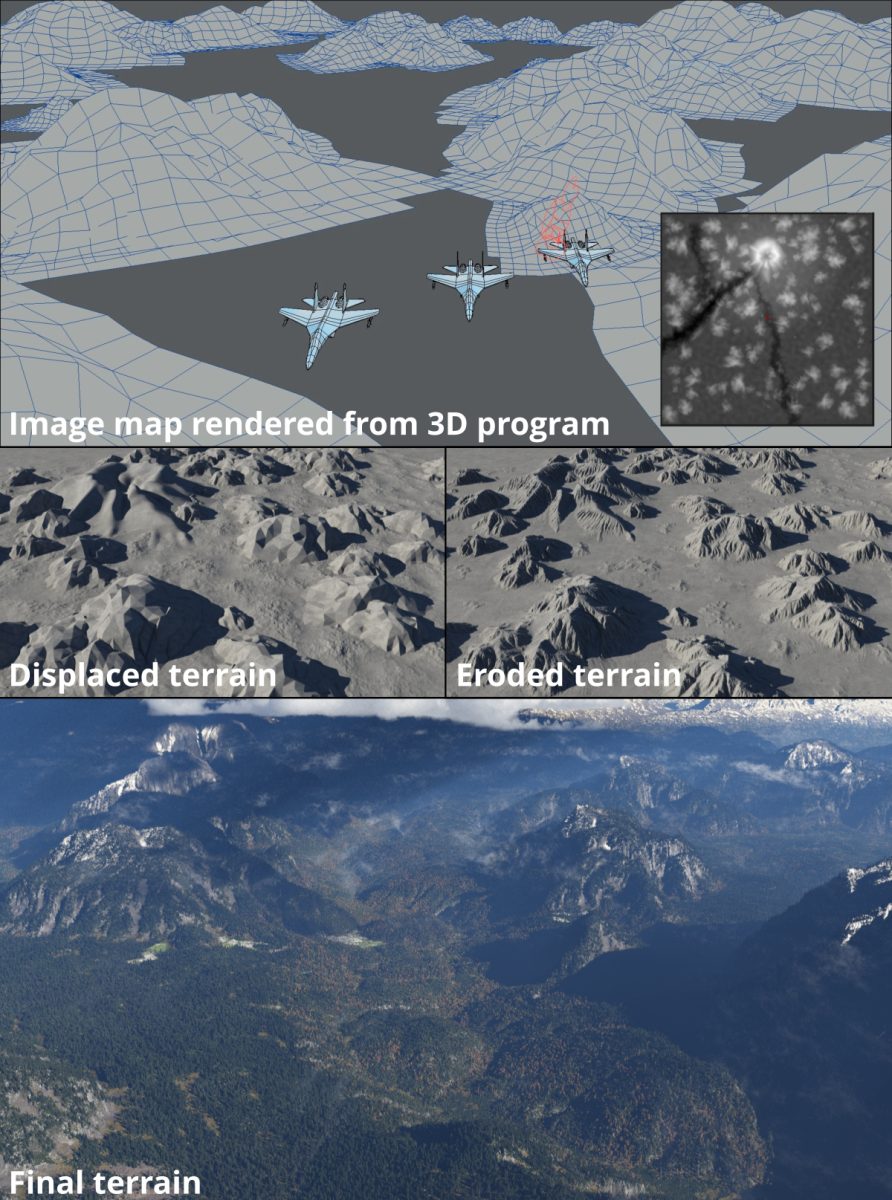
In the video tutorial series, Terragen for VFX, we created an image map for the entire terrain using a particle system in a 3D program to distribute several mountain-shaped objects across a scene. The image map was rendered with an orthographic camera high above the terrain and pointed towards the ground.
You can also create unique environments by randomly “splattering” image maps across the terrain, then warp and erode the displaced terrain.
Try It For Yourself
Click here to download a Terragen 4 project file that includes examples and step-by-step instructions for the Image Map shader workflow described in this post.
Other Posts In This Series
We hope you are beginning to see the value in using Image Map shaders to construct art directable terrains. Like the Simple Shape shaders, these are easily manipulated in the Terragen project file, and the ability to distort the images and apply erosion operators allow for almost unlimited terrain possibilities.
Click on the thumbnails below to discover other exciting Terrain Techniques!
